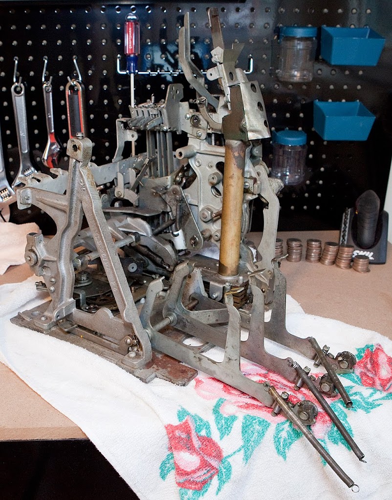
The last parts left connected to the base plate are all related to the payout system. A word of caution before we proceed: As we remove the horizontal fingers and the payout slides, it’s important to keep them in order just like we did for the vertical fingers a few chapters ago. We’re going to try to remove the entire horizontal finger assembly as one unit, but if it becomes necessary to dismantle it I’m going to thread a piece of wire through the parts to keep them in order. The same thing goes for the payout slides.
Anyway, let’s get to work.
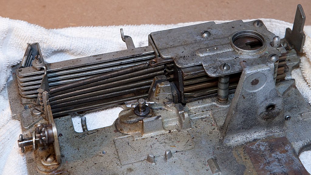
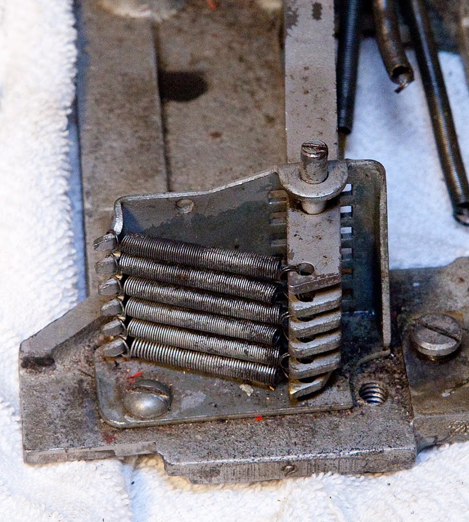
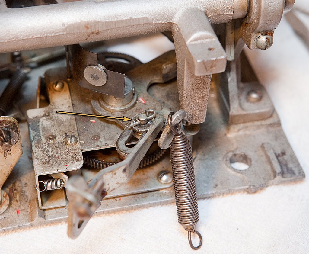
Here we see the horizontal fingers and the payout slides. We can go ahead and disconnect the large springs for the payout slides and the small springs for the horizontal payout levers at any time.
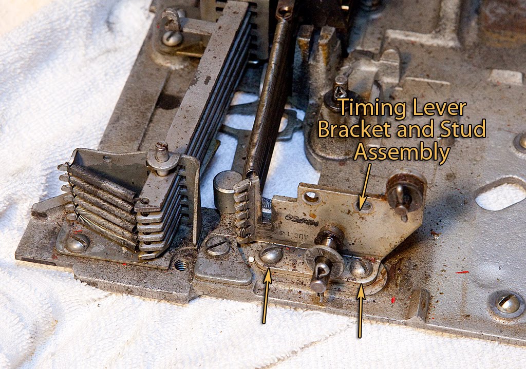
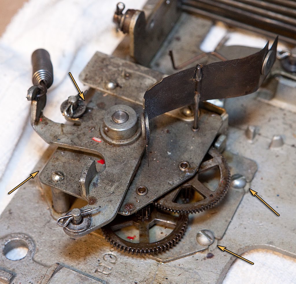
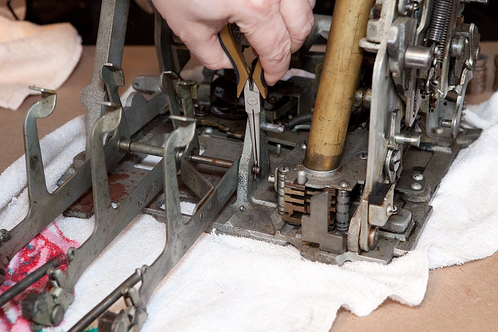
The photo above shows the first part we’ll be removing. Since the springs for the coin slides are connected to it, we need to go ahead and slip them off of the ears on the timing lever bracket. Once the springs are free, we can unscrew the two screws pointed out above to remove the part.
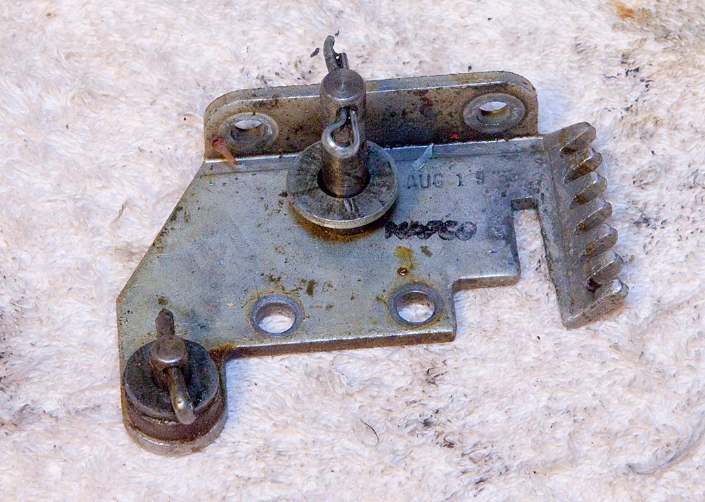
You’ll notice that there is a partial date printed on this particular piece, but that will not always be the case. Sometimes when you tear into an old machine you find bits of information like this, which is sometimes useful but often confusing.
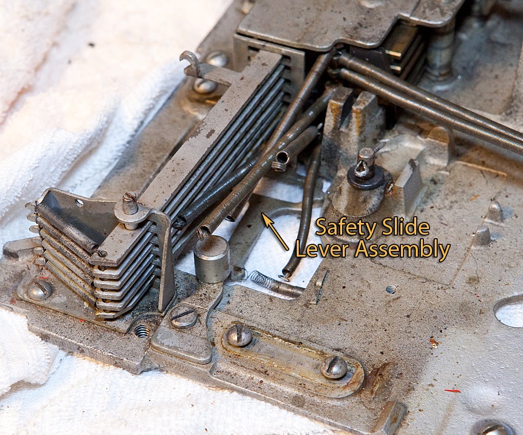
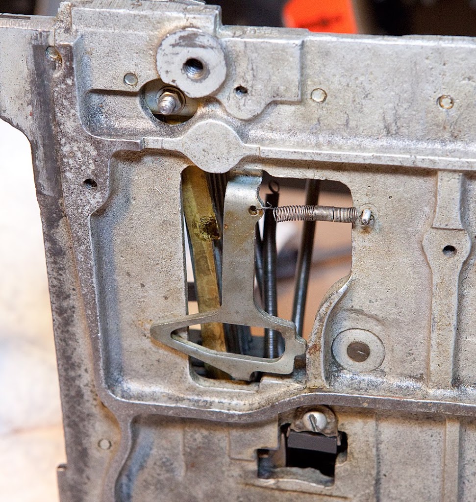
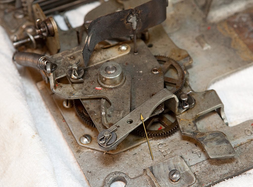
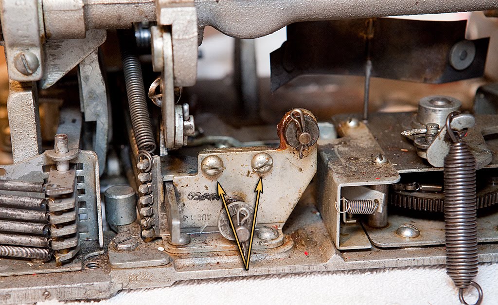
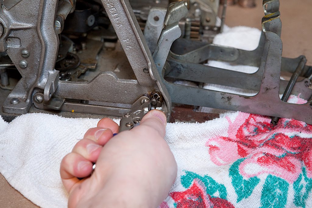
The part in the photo above can be removed at this point, although it is probably easier to wait until the coin slides are removed. I chose to remove it now, so that’s what the photos reflect. It’s secured by a shoulder screw visible in the photo above, plus a spring that is attached to the underside of the base plate.
The safety slide lever assembly is the closest thing an antique slot machine has to a pinball machine’s “tilt” mechanism. When we remove the payout slides you will be able to see the safety slide itself, which is really nothing more than a thin piece of metal with a hole in it. It its normal position, it allows coins to pass down through it and out of the mechanism into the payout chute. If the machine has been jarred during its cycle, however, the lever trips and the slide moves backwards to prevent coins from passing through.
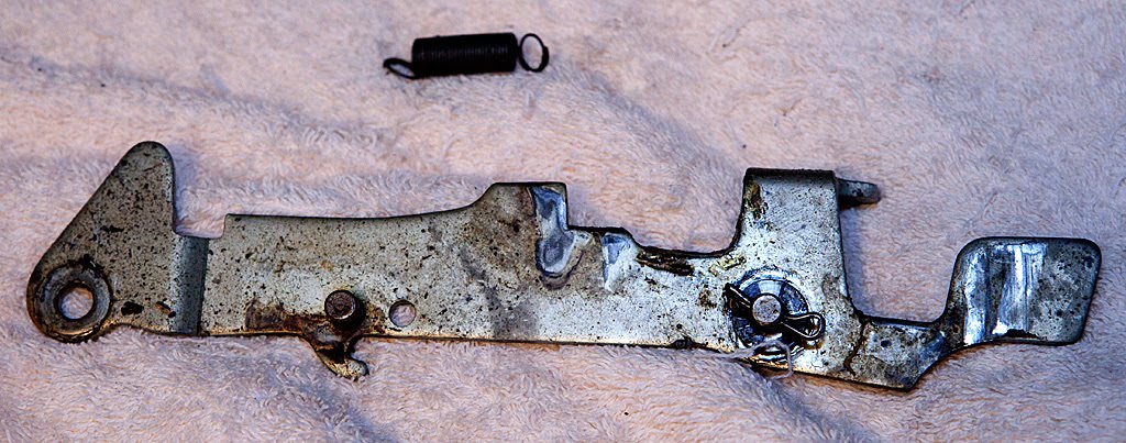
The entire safety slide/lever mechanism is sometimes called the “non-beating” mechanism for obvious reasons. Although these are relatively minor parts, they sometimes cause problems. If the small spring attached to the safety slide lever breaks or loses tension, or if the lever gets generally gummed up, the safety slide can travel backwards on every pull of the handle, preventing the machine from paying off. For this reason, if you have a machine that won’t pay off at all you should probably spend a bit of time checking to be sure that the lever travels freely and that the attached spring returns it to its proper position.
Here’s a view from underneath the base plate:
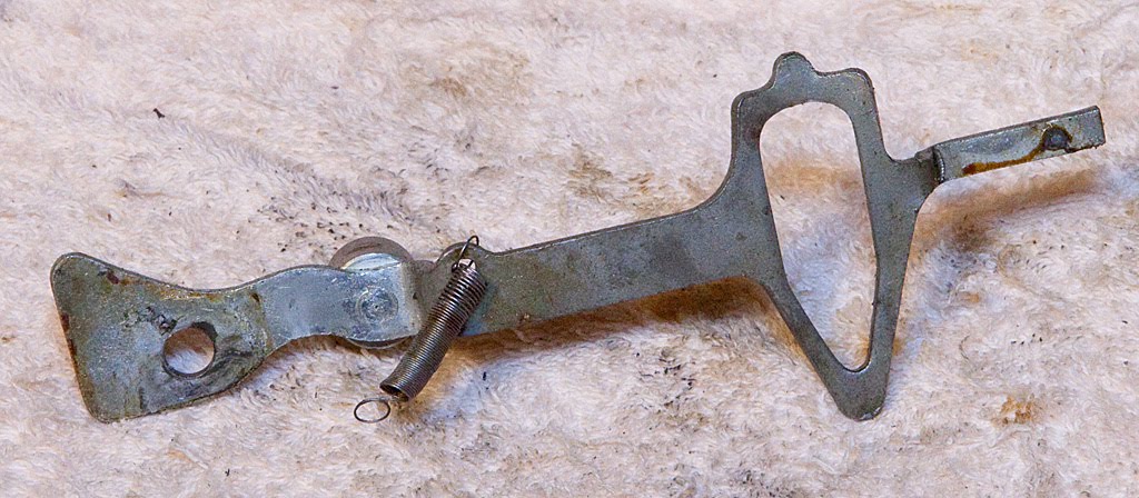
Once the shoulder screw is removed and the spring is disconnected the lever can be removed, although it takes a bit of maneuvering to get it out from under the coin slides. For this reason, you may want to leave it in place for now and remove it later.
Next, we’re going to remove the horizontal fingers and the related bracket as one piece if possible. If you haven’t already disconnected the springs shown below, go ahead and do it now.
In the photo above you can also see the screw-in shaft that secures all of the horizontal fingers, and it’s perfectly OK to take this shaft out and remove each finger individually. In fact, that may be easier all around. I’m going to leave the shaft in place for now, though, and try to remove the entire assembly at once.
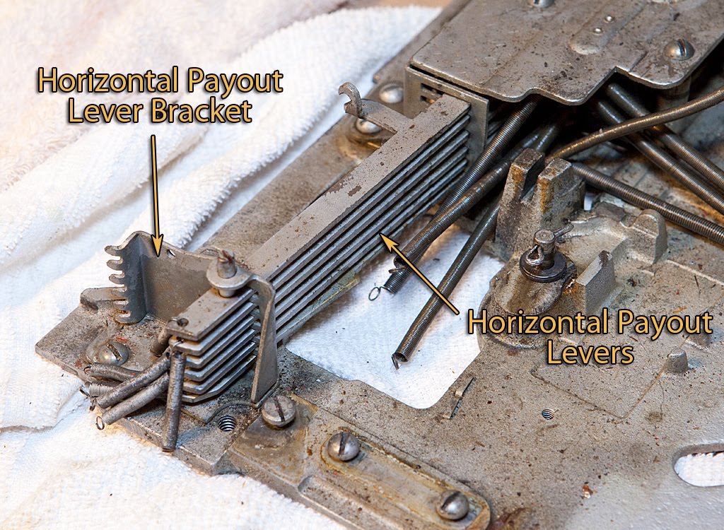
The horizontal payout lever braket is secured to the base plate with a couple of screws. Once they are removed, if you are trying to remove all the fingers one at a time or all at once, you will have to work them backwards GENTLY to get them out of the guide bracket up near the slides (seen near the top of the photo above.)
Sometimes there is a spacer underneath the horizontal payout lever bracket, so be sure to watch for it and replace it when you reassemble the machine.
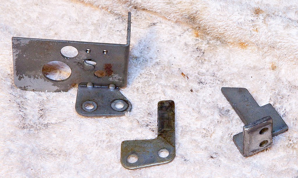
Let’s see what the assembly looks like once we have the assembly off the mech:
All of the fingers look the same, except for the very top one which has the hook for the spring that I destroyed earlier in the teardown (the jackpot finger), and the bottom one which has a protrusion on the front edge (the one-cherry finger.) Even though the middle four fingers are essentially identical, that doesn’t mean that you shouldn’t keep them in the same order when you reassemble the machine. Parts wear together over the decades, and changing them around can sometimes cause you problems.
You may also notice in the above photo that some of the fingers are bent a bit on the right-hand side. If you encounter parts that are bent inside of an antique slot machine, your first instinct may be to straighten them out immediately. This isn’t always a good idea. Bending was a common and accepted adjustment in most antique slot machines. Until you are certain that a bend is causing you problems, you should probably leave it alone. There’s a good chance that someone who knew more about slot machines that you do put the bend in the part intentionally a long time ago, and you don’t want to inadvertently undo their good work.
Anyway, back to the mech:
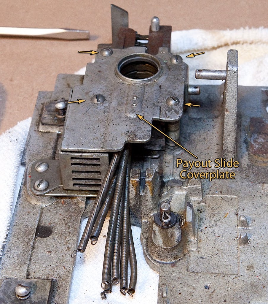
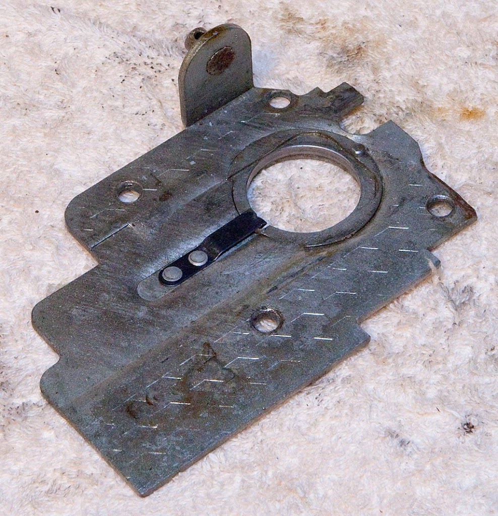
Four screws secure the payout slide coverplate. Here’s what the underside looks like once it has been removed from the mech:
With the cover removed, we can finally see the coin slides themselves:
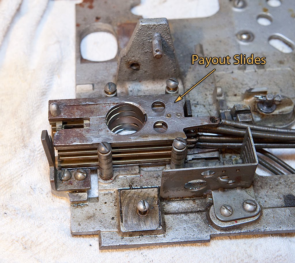
At this point, the slides are not secured to the mech by anything, and can be lifted straight up. Be sure to keep them in order!
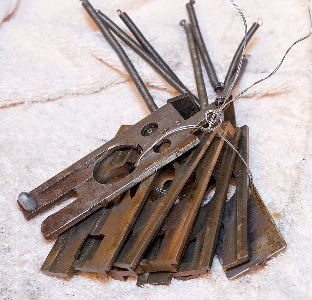
Notice that I’ve tied the slides together with a piece of wire to keep their order straight. Remember our discussion regarding the number of coins held in each slide? Here’s a visual:

We’ve only got a few parts left to remove, and they are all secured with basic screws.
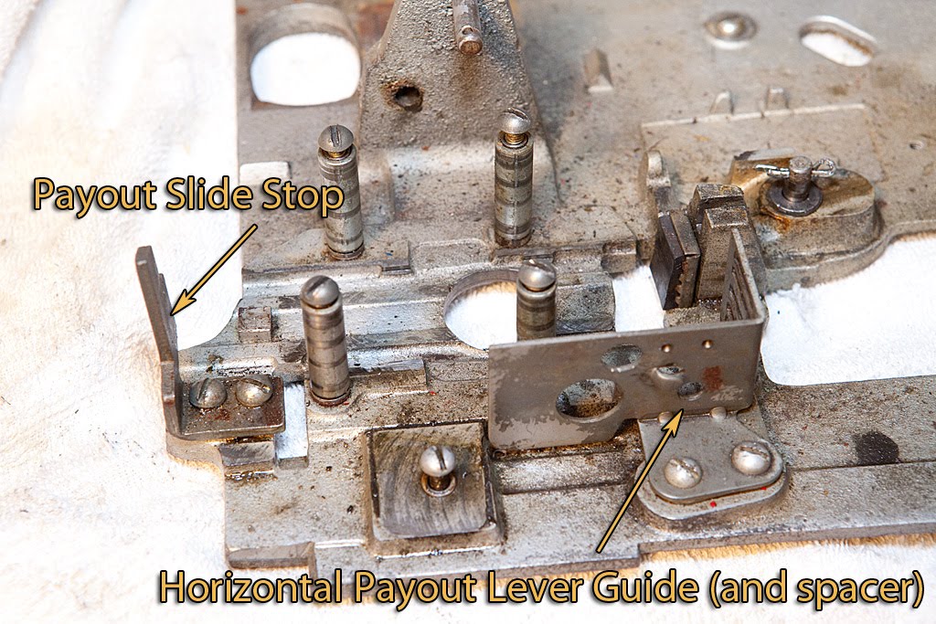

Don’t misplace the spacer shown above. Without it installed, the horizontal fingers will bind in the guide and not work properly.
We’ve got another bumper that needs to be removed. This one stops the payout slides at the back, making sure that their holes line up over the circular hole in the base plate that leads to the payout chute.
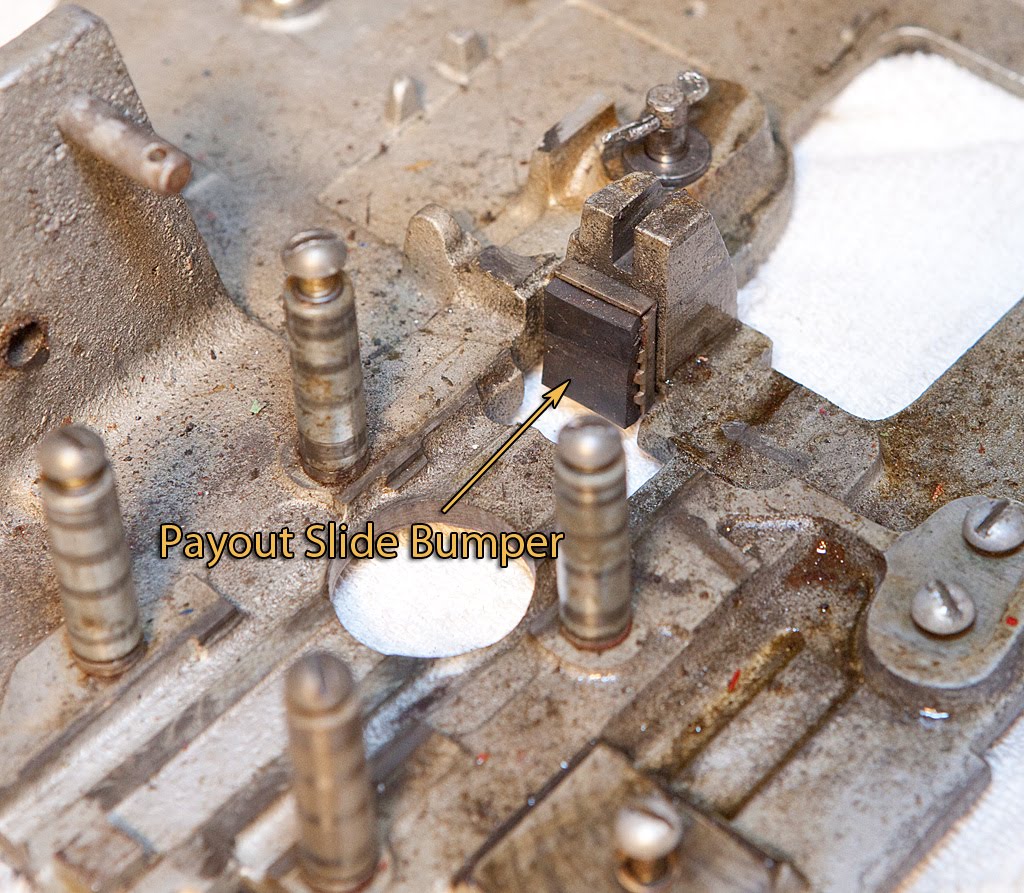
It’s secured on the underside of the base plate with a screw.
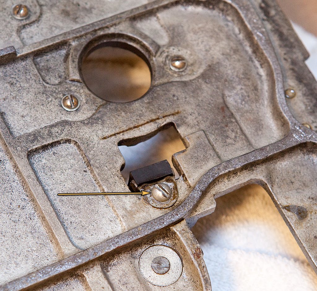
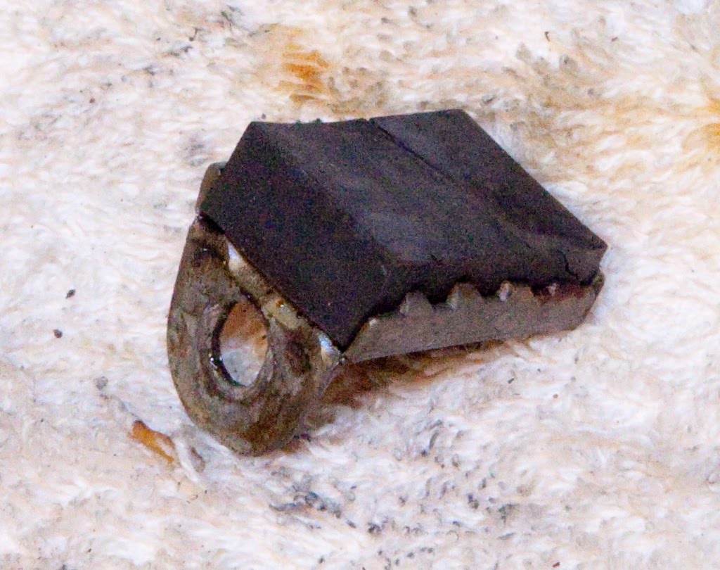
This bumper is in better shape than the others we’ve seen, but it’s hard as a rock and will probably also need to be replaced.
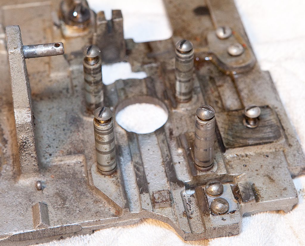
There are four posts that held the payout slide coverplate that could be removed from the base plate now, but in general it’s not necessary to remove them unless you are doing something extreme to the base plate. I’m going to leave them in place for now.
Believe it or not, that’s it! We’ll have some minor disassembly to do as we clean the various parts of the mechanism, but we’re done with the mech for now. Check it out:

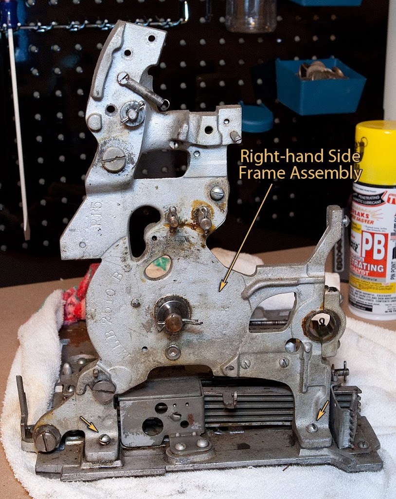
From this point forward, most of the disassembly of the slot machine mechanism is pretty straightforward and doesn’t need a lot of explanation. The order in which you remove parts usually isn’t critical; as long as you can get to the parts easily and remove the necessary screws and springs the part is probably safe to remove. By the time we finish this section we’ll have the entire right-hand frame removed from the mech. Let’s get started.
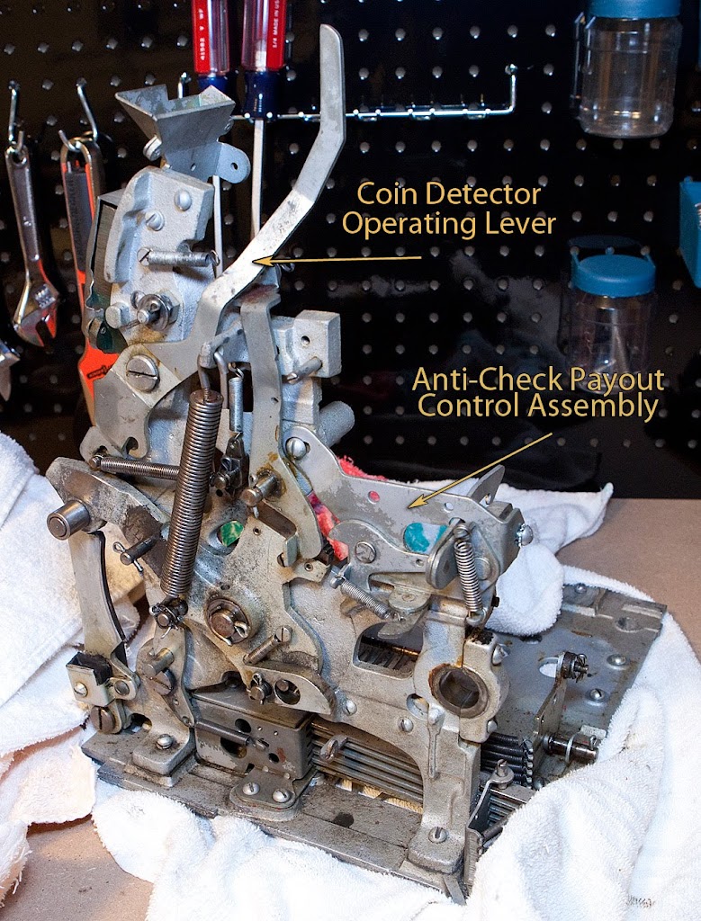
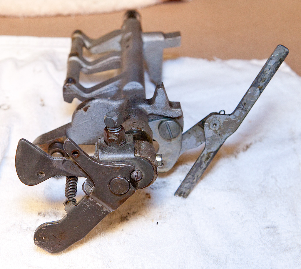
The two parts highlighted above are pretty easy to remove. The coin detector lever should be familiar to you from our earlier discussion regarding the operation of the mechanism outside of the cabinet. This lever interacts with the escalator to determine when a coin has been inserted, and in turn allows the mech to cycle. We’ve also discussed the anti-check payout control assembly at some length. Both should come off the mech easily at this point. The coin detector lever is held in place with a shoulder screw.
If you aren’t familiar with term “shoulder screw” this photo should make the concept clear:
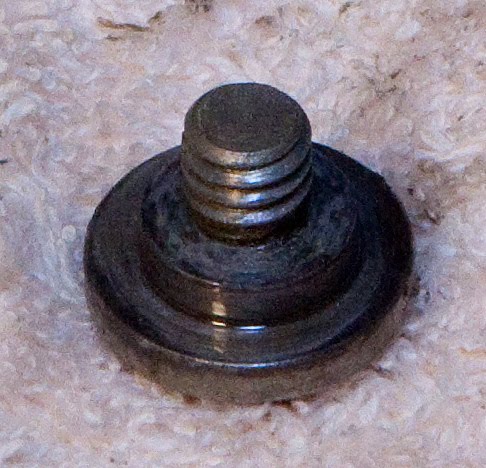
As you can see, the threads of the screw don’t extend all the way to the head, and there is a “shoulder” between the head and the threads. That shoulder is the surface upon which the lever rotates.
Back to the anti-check payout assembly, it is held in place by two screws: one at the back of the mech, and another on the side. They should be easy for you to locate.
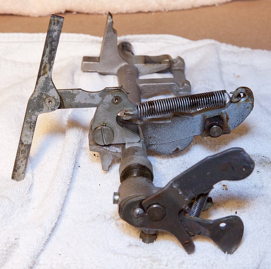
Once you have this assembly off the mech, be sure to play with it a bit to get a good idea of how it operates, particularly if you intend to reinstall it and leave it in working condition rather than applying the “fix” we discussed earlier.
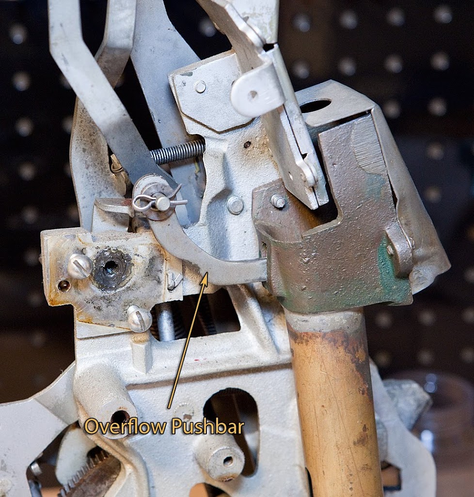
Now let’s move on to the overflow pushbar assembly.
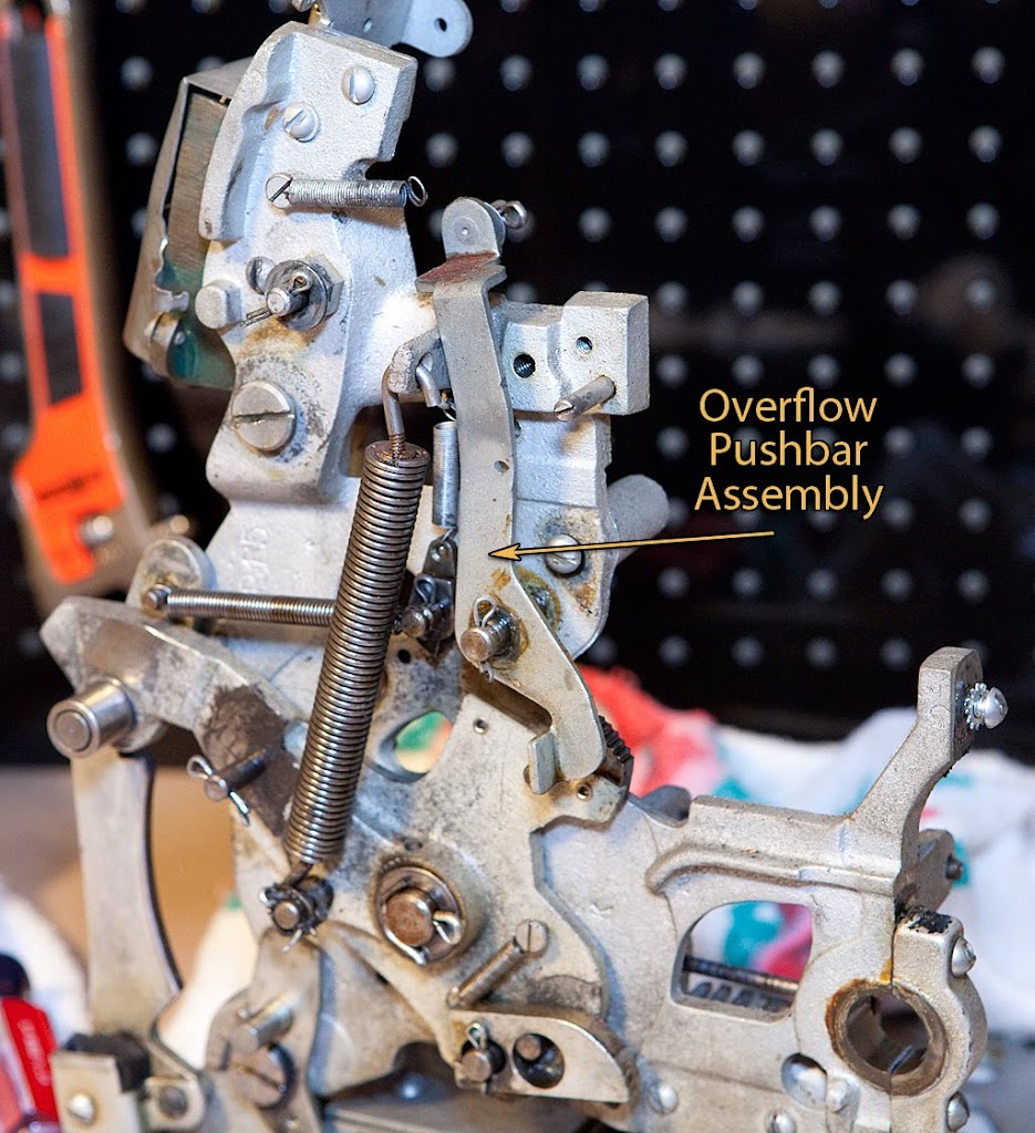
We’ve already removed the pushbar itself in an earlier step, but this is the lever that actually operates that pushbar which keeps the coin tube from overflowing by pushing coins into the jackpot assembly.

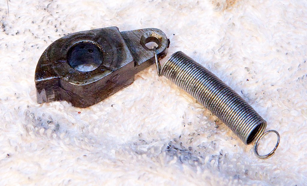
Moving right along, let’s look at the operating fork dog.
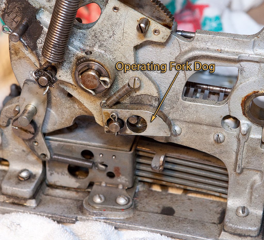
Removing the cotter pin and the related spring frees this up to be removed.
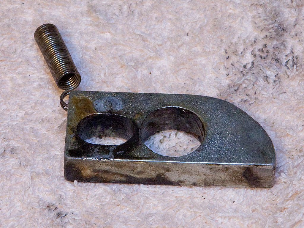
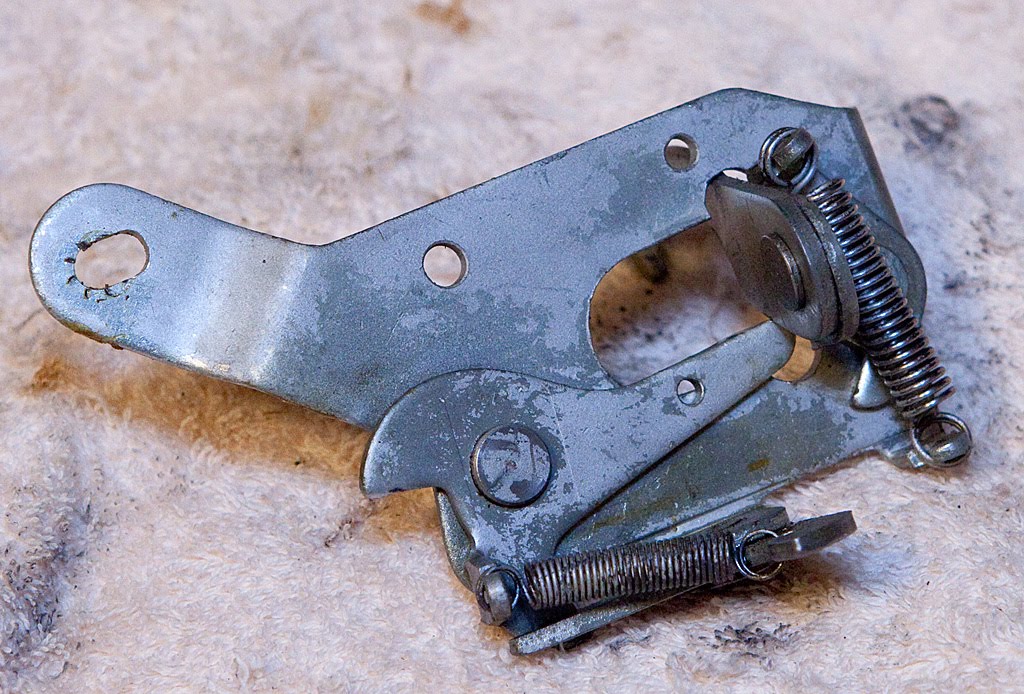
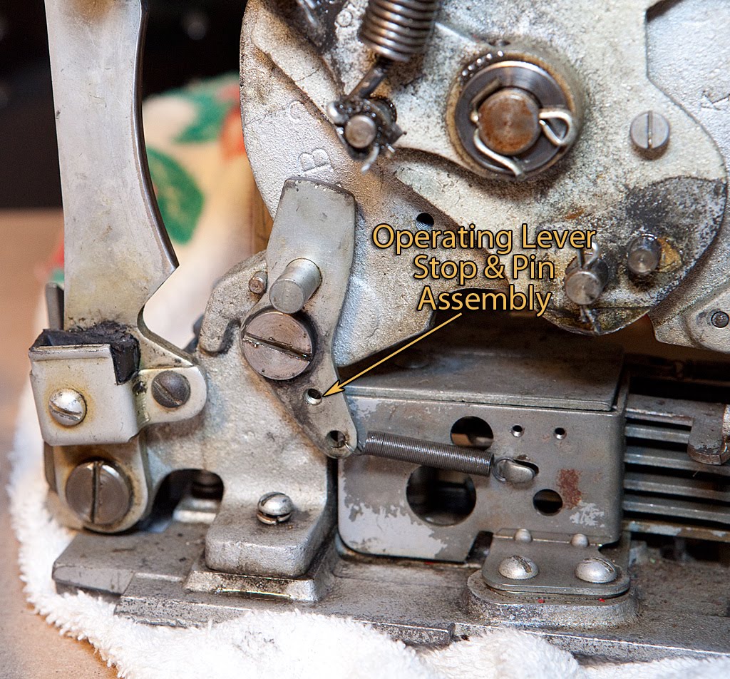
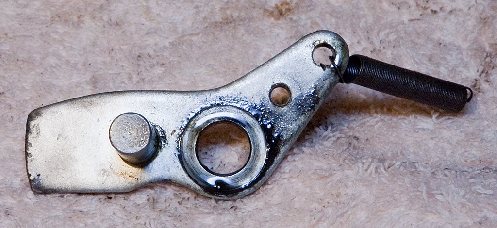
Another easy part to remove is the operating lever stop pin, which is secured by a single shoulder screw and related spring.
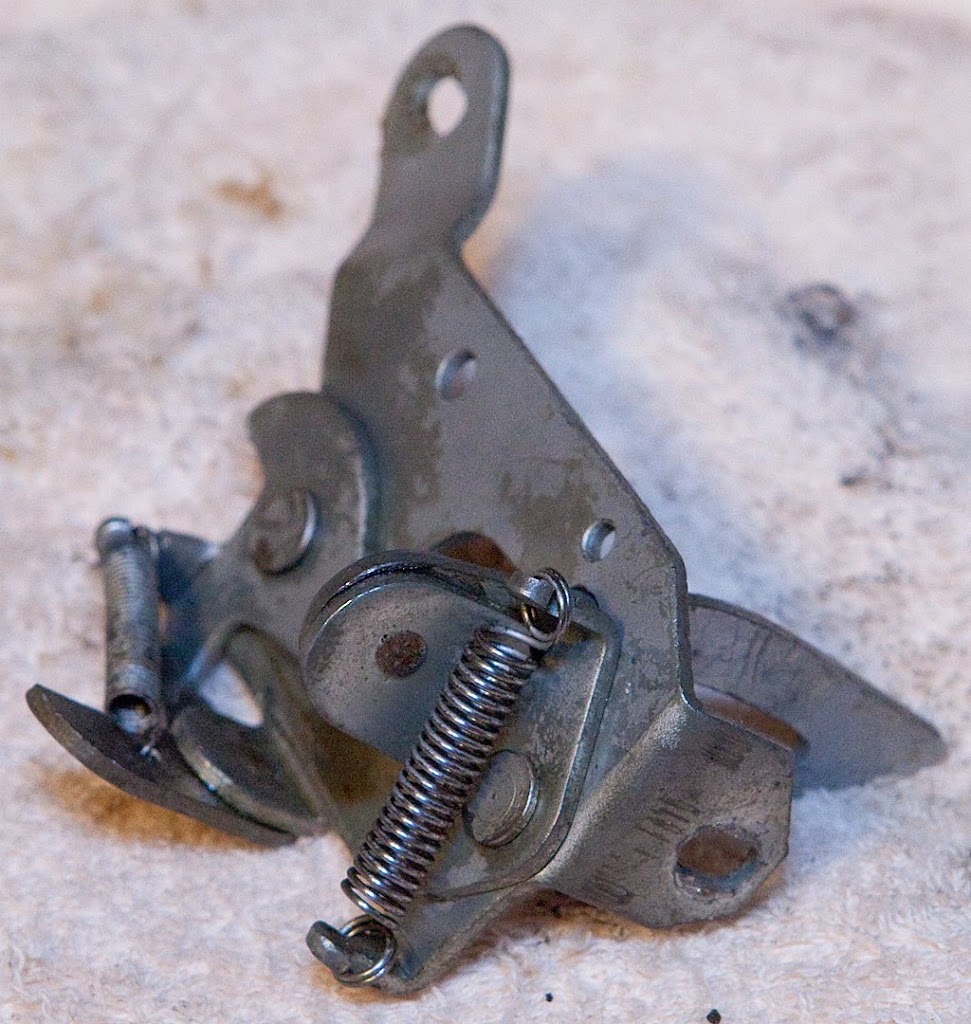
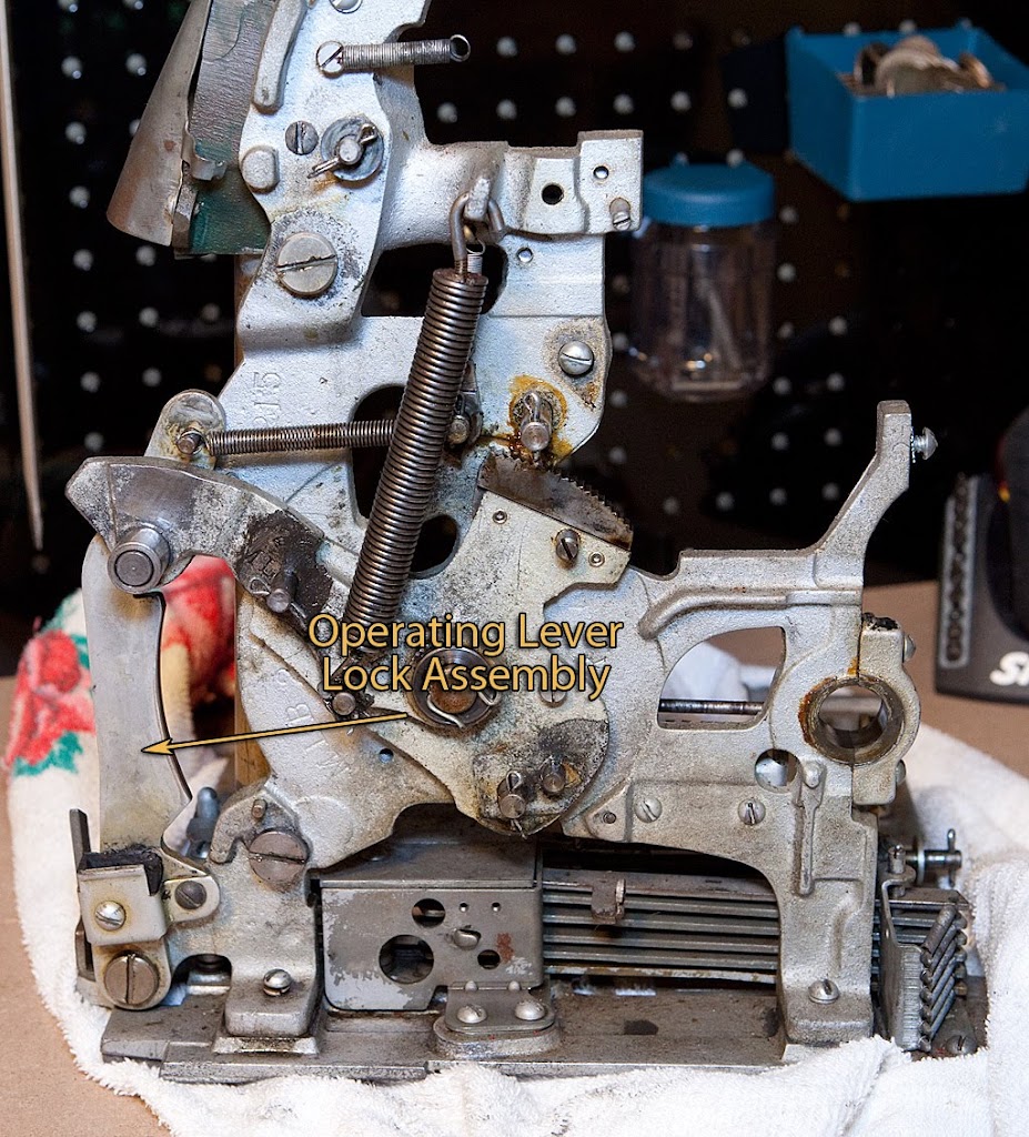
The operating lever lock assembly is ready to come off, and again we need only remove a single shoulder screw and related spring.
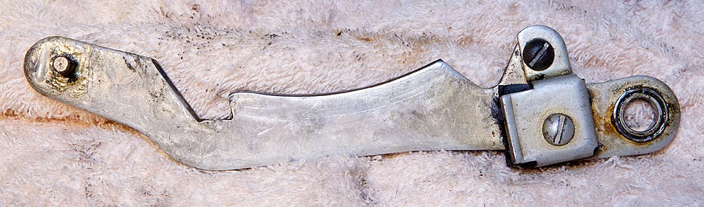
Let’s take a closer look at the rubber bumper attached to this piece:
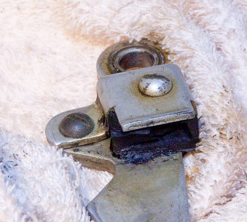
Yuck. This part obviously isn’t doing much good since it has almost totally disintegrated. We’ll have to replace that before reassembling the machine.
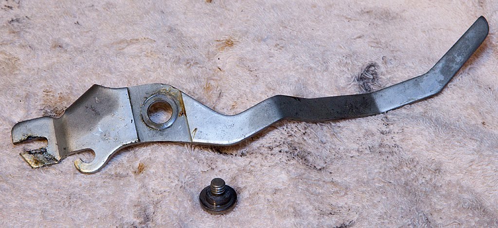
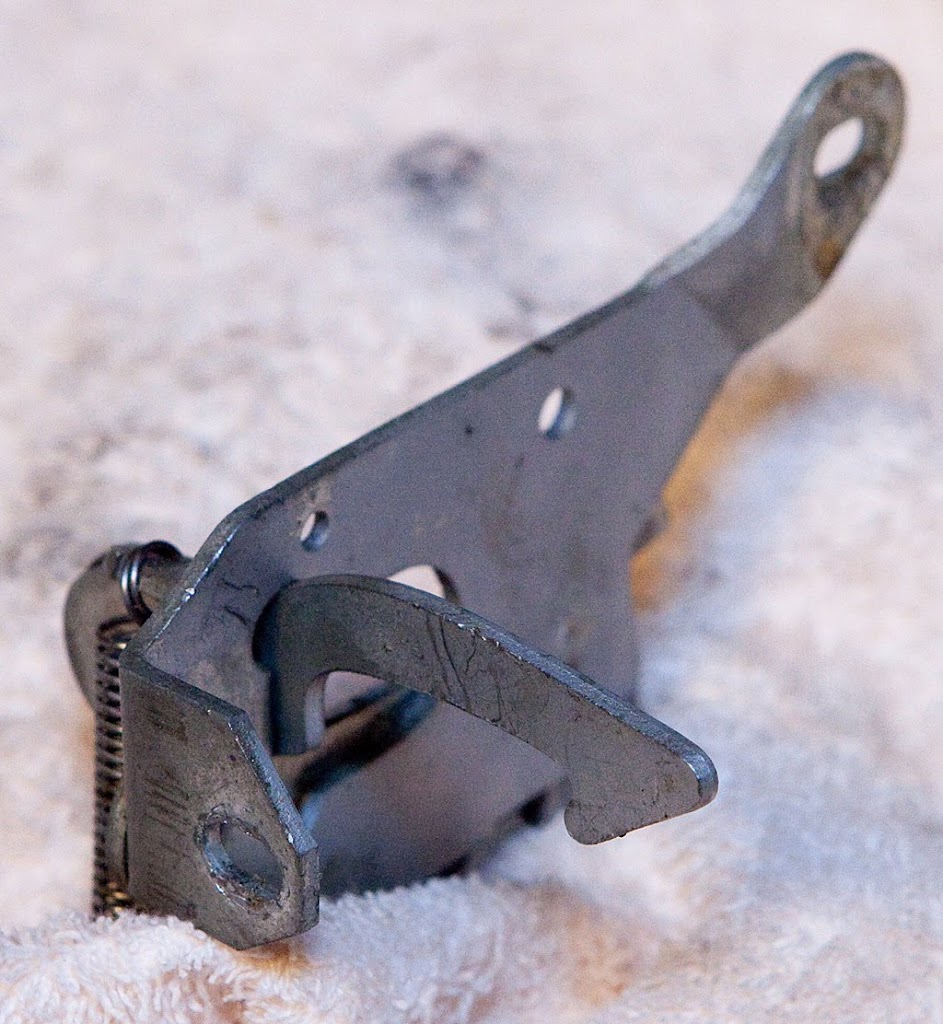
Now we’re ready to remove the main operating lever.
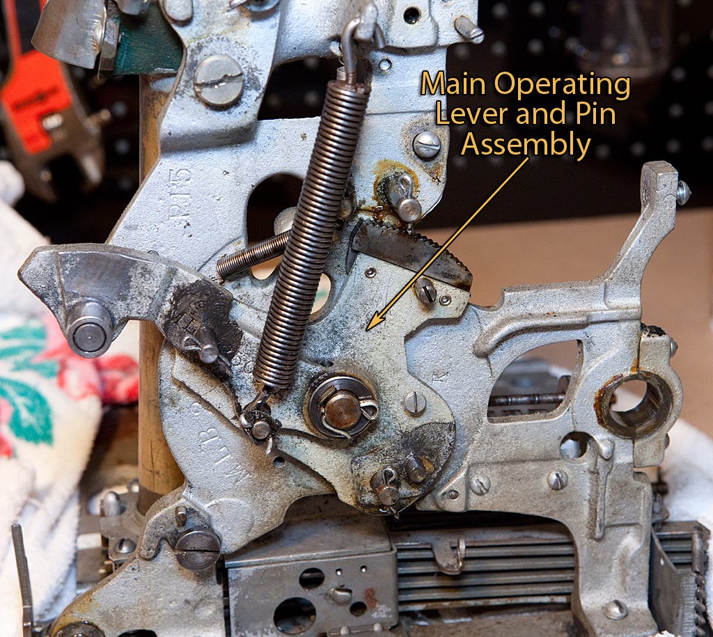
Once again, a single cotter pin and a spring attach it to the frame.
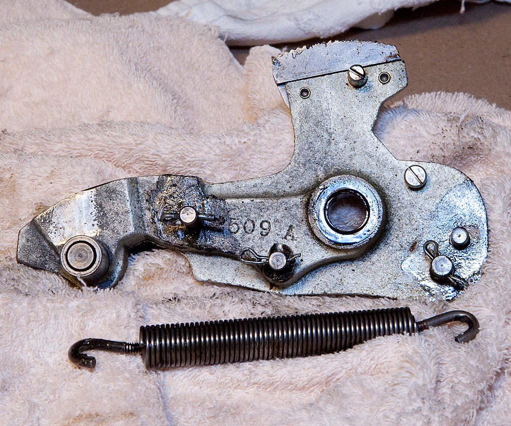
This is a very substantial part that does the job of transferring energy from the handle to the mechanism itself. We’ve also got another small dog to remove, and it’s no more difficult than the last one.

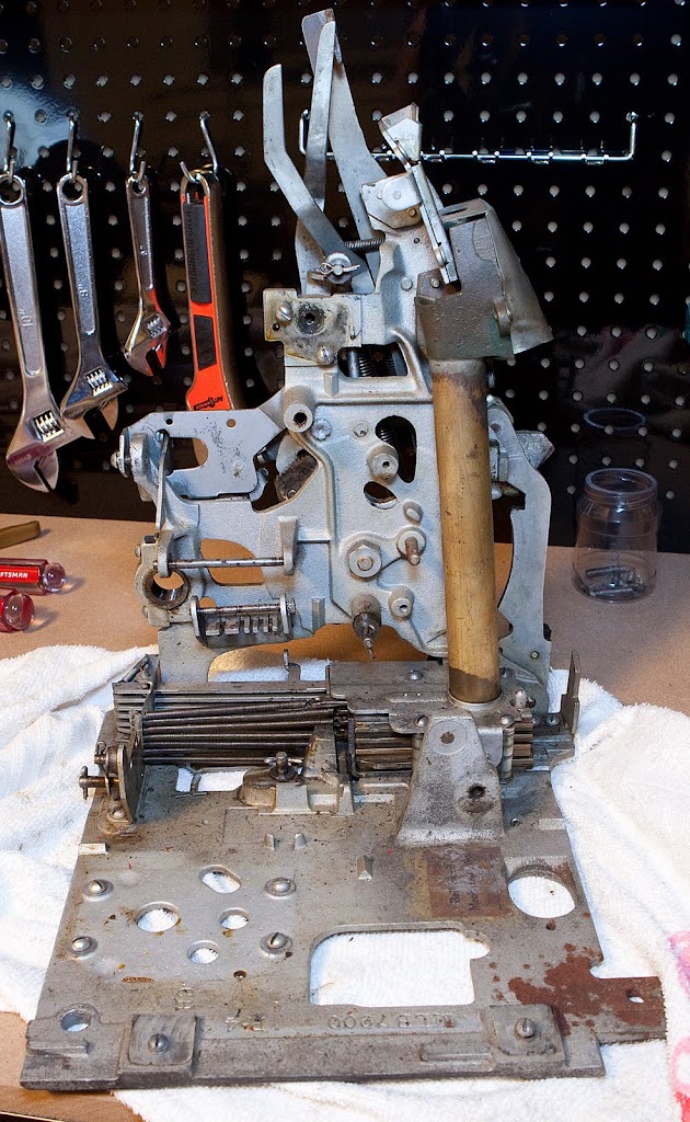
The frame is starting to look pretty bare… take a look.
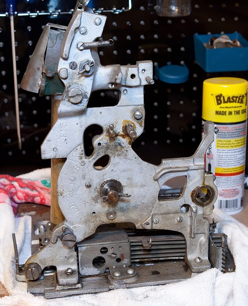
The only parts attached to the frame that need to come off prior to the removal of the frame itself are related to the coin tube, and they are only secured by a couple of screws.
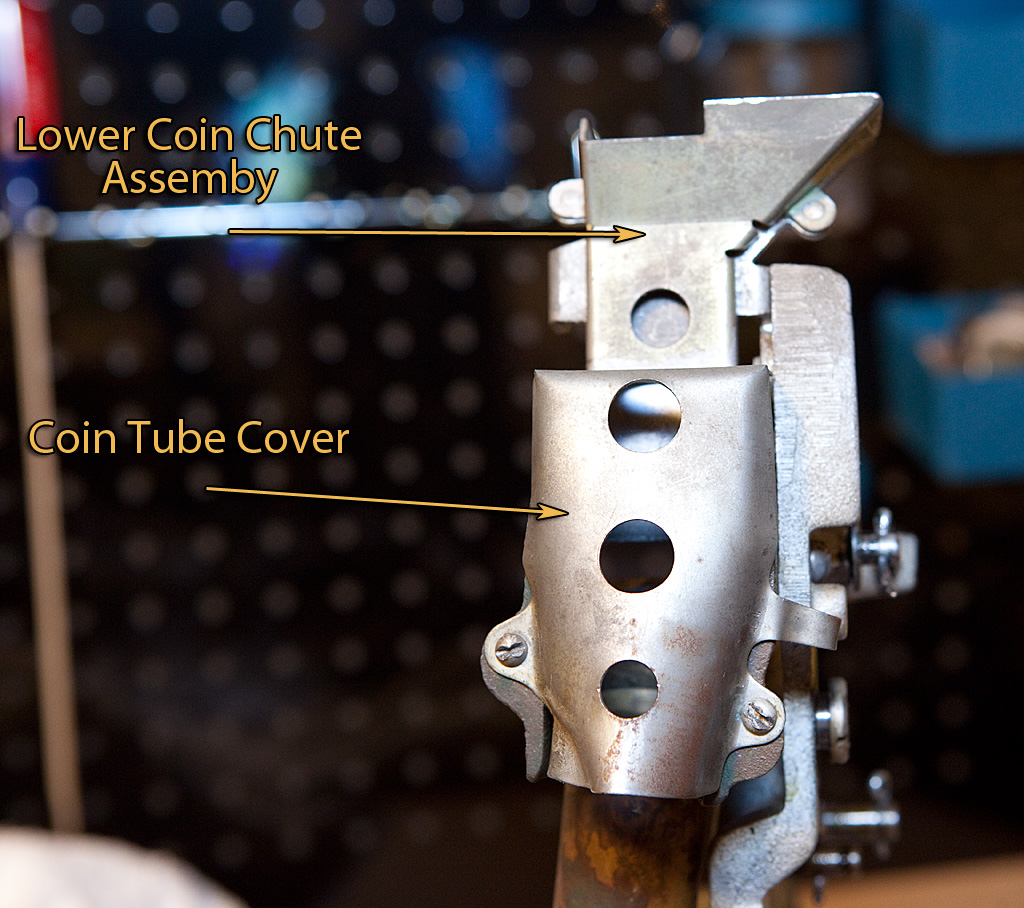
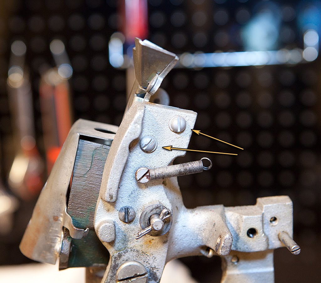
The lower coin chute assembly is secured to the frame by a couple of screws shown above, and the coin tube cover is attached to the coin tube by a couple of screws that should be pretty obvious.

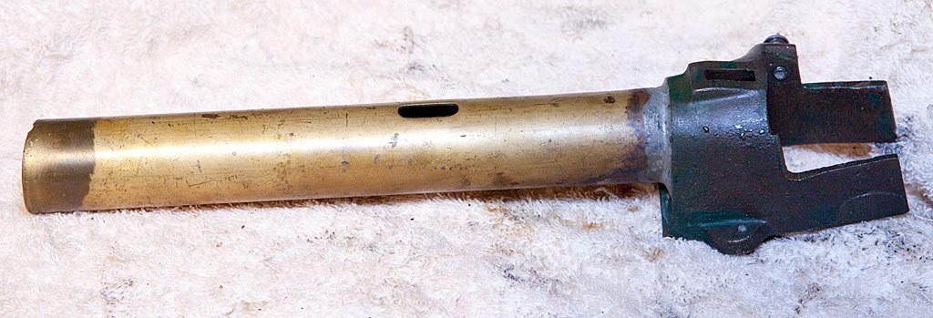
Now, on to the coin tube itself.

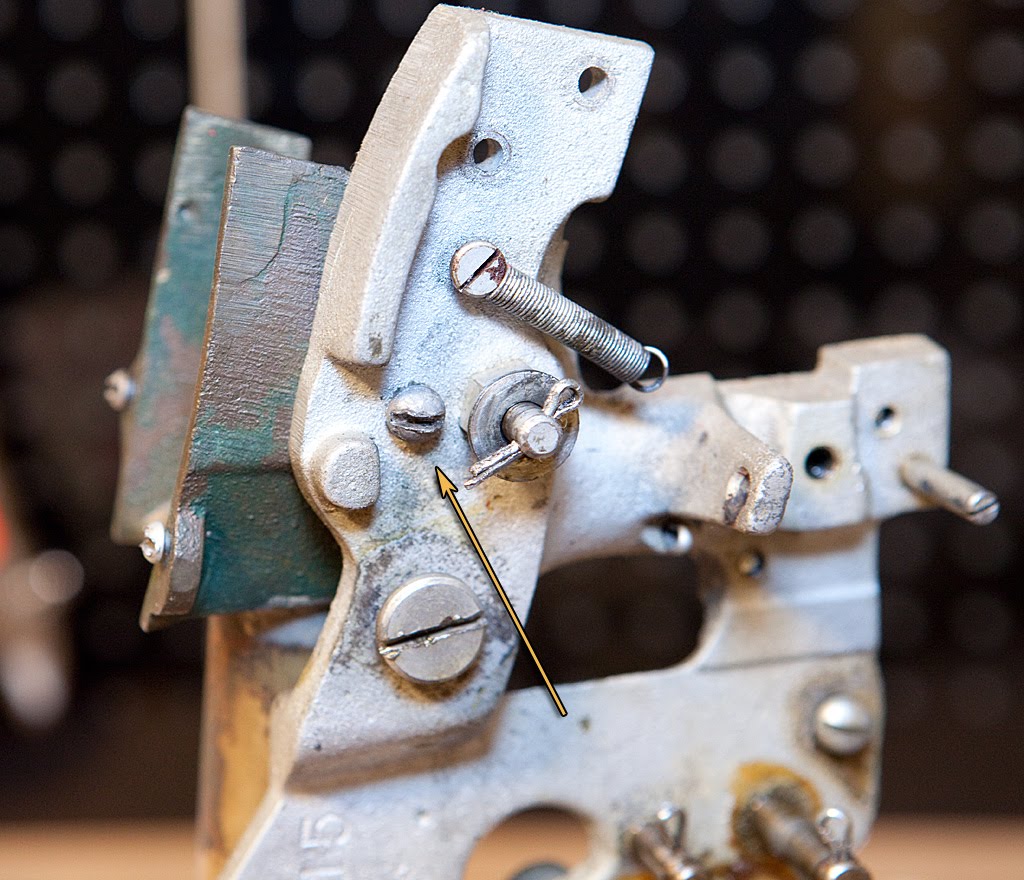
The coin tube is where all the coins used for non-jackpot payouts are stored, and is connected to the frame by a single screw pictured below. Once the screw is removed you can lift the tube straight up.
That’s the last of the parts that need to be removed from the frame… now we can remove the frame from the base plate by removing two screws as shown below. These two screws are sometimes difficult to remove, so you may need to apply some WD-40 or a penetrating solvent like B’laster. Just a quick word about B’laster… it’s wonderful stuff. It may not free up every frozen, rusted screw, but it does a heck of a job. It’s great stuff to have around.
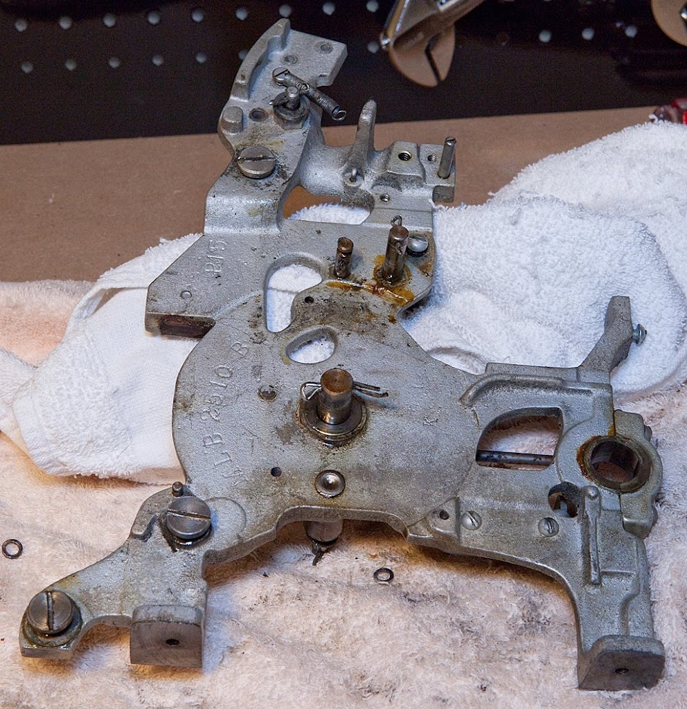
In the photo above you can see the two shafts we removed and replaced earlier, along with another bumper that probably needs to be replaced. Let’s take a look at what’s left of the mechanism.
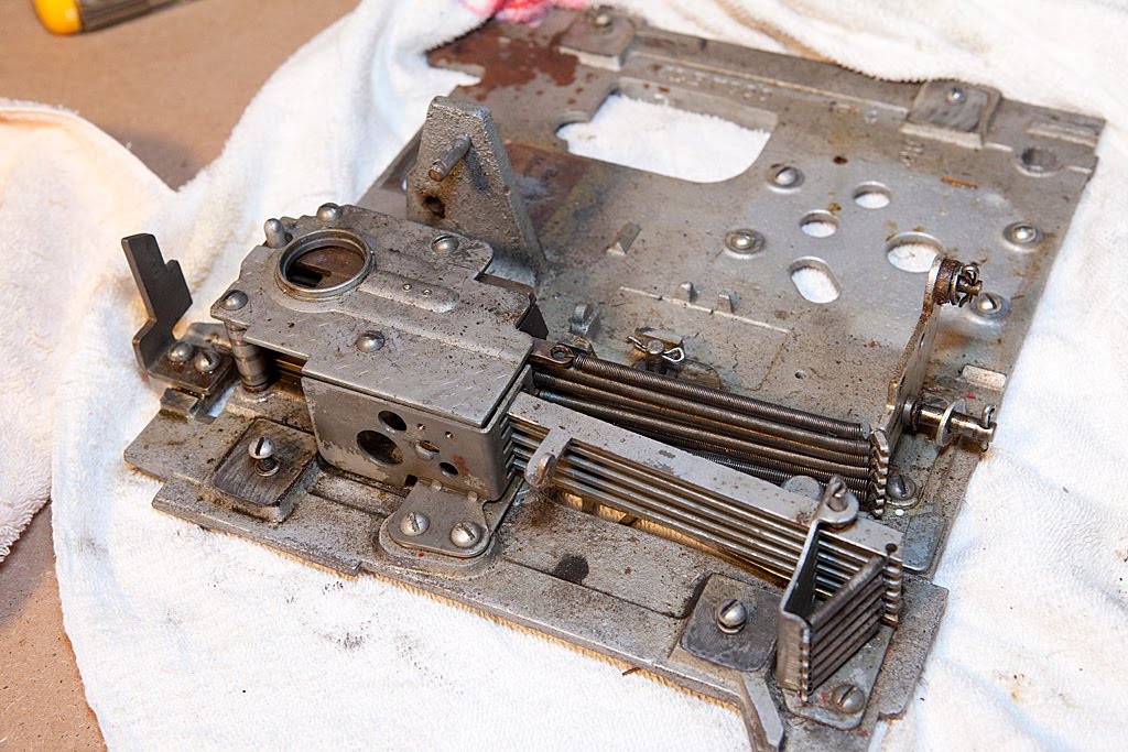
All of the parts left on the base plate are related to the horizontal payout levers or the coin slides. We’re in the home stretch now, and we’ll tackle those parts next.
The next three parts are a snap to remove. First, the overflow pushbar.
Secured by a single cotter pin, this part pushes coins off the top of the payout tube once the tube is full. The excess coins are then routed to the jackpot assembly and ultimately the cash box if the jackpot is full.

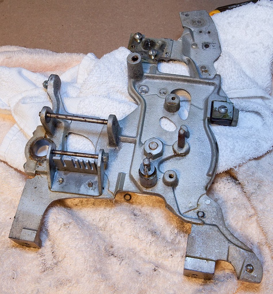
Let’s take a quick look at the slot machine mechanism… it’s really starting to look bare.
Now we need to turn the mechanism around and work on the other side for a while. First, let’s remove the check detector operating arm assembly.
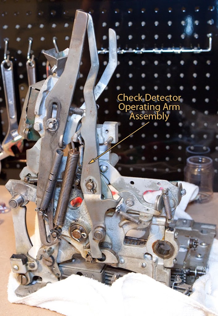
If you look carefully at the photo above you can see how this operating arm engages the anti-check payout control parts we looked at earlier. If the check detector arm is allowed to move forward by the escalator because of a check being played (there’s a special pin to sense the hole in the middle of a check) then the arm trips the anti-check payout control lever, allowing the anti-check payout hook to drop. This, of course, would hold the vertical payout pushback lever in place, restricting the movement of the vertical fingers and disallowing any payouts of coins as we discussed in the previous chapter. It’s a neat system, when it works.
The check detector operating arm assembly is secured by a single cotter pin, with an attached spring near the top of the arm.
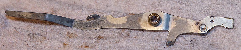
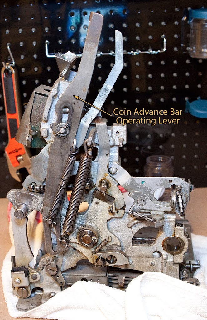
Now we’re going to remove the coin advance bar operating lever, which is easy to pick out in the photo below.
This part interacts with the escalator at the beginning and end of the mech’s cycle, releasing and resetting the coin advance bar locking lever which allows/restricts the advance of coins across the escalator. It’s secured by a couple of cotter pins and a spring, so those need to be removed.
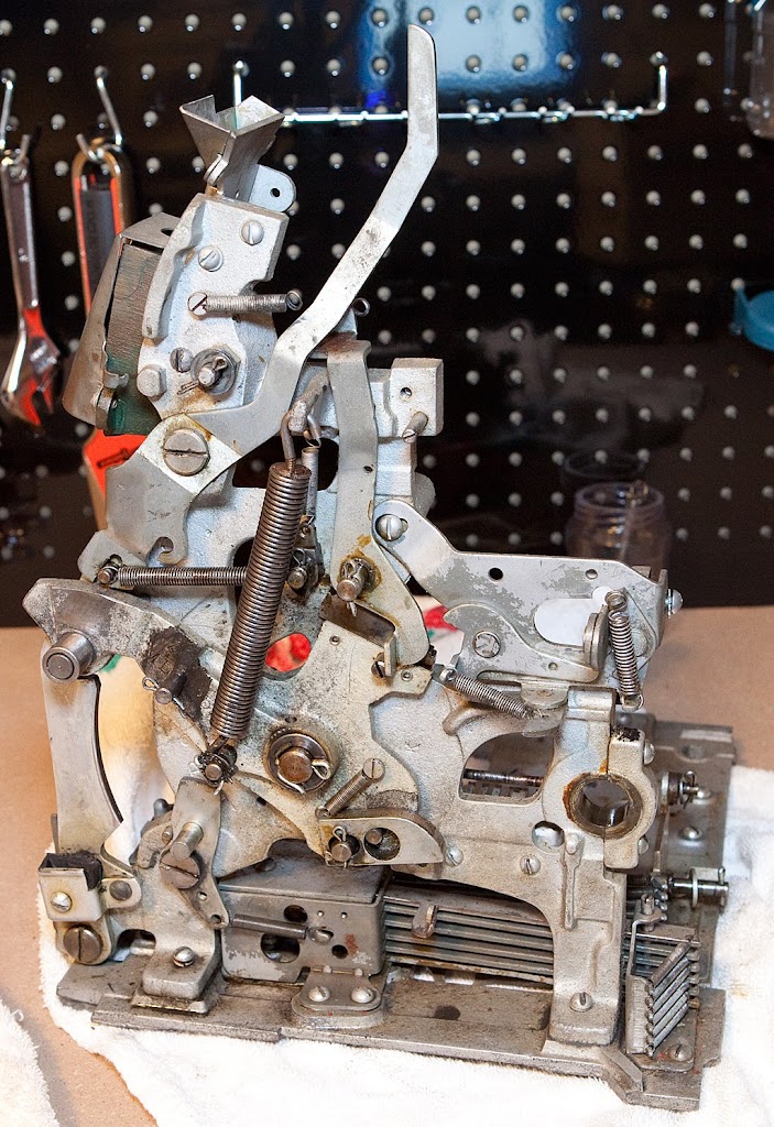
Let’s take another look at the mechanism before we proceed. We’ve made a lot of good progress.
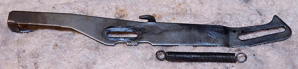
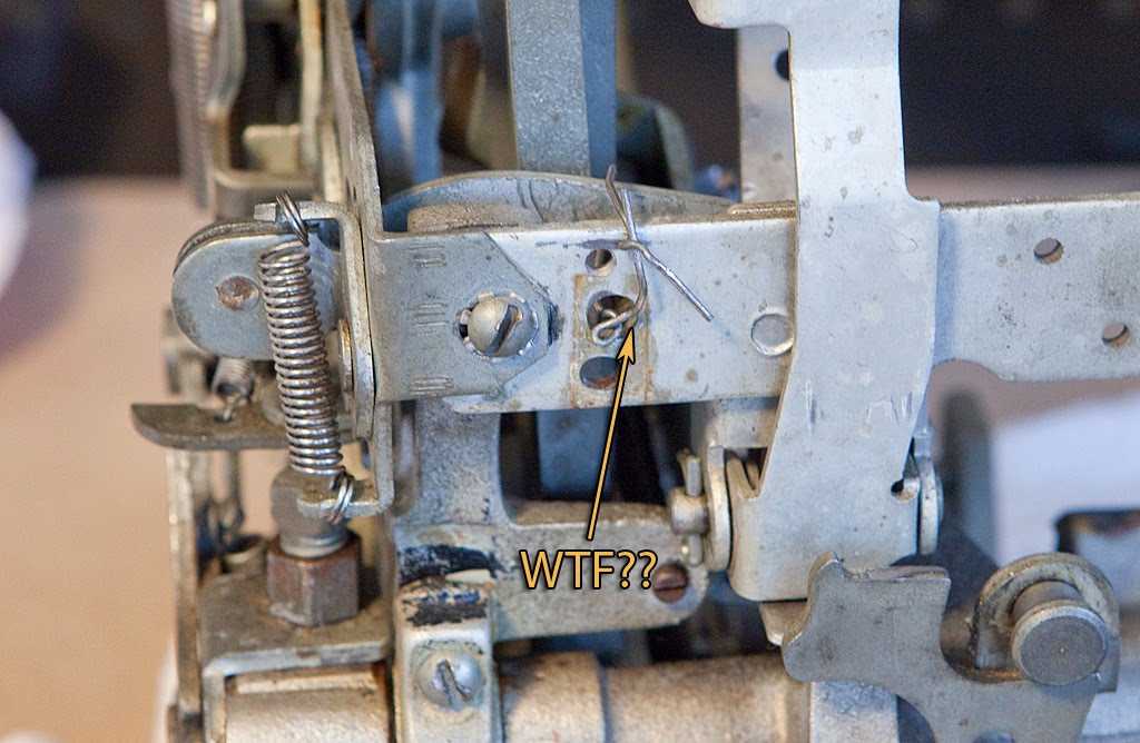
Now it’s time to remove the long-named “vertical payout pushback lever assembly” which is a complicated name for a relatively simple part.
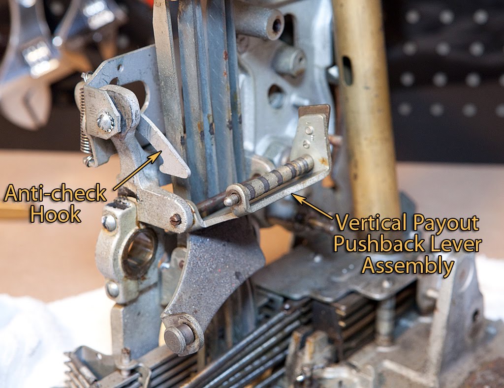
The name of this part tells you pretty much exactly what it does, specifically pushing the vertical fingers back away from the payout discs at the beginning of the cycle. It’s attached to the machine with a screw-in shaft, seen above just below our old friend, the anti-check hook. Now that the parts are uncovered, you should be able to see exactly how this troublesome part works. If you look at the portion of the pushback lever assembly that looks like a roller, you can see several places where it looks like something has “grooved” the roller. These spots are where the vertical fingers have worn the roller as it has pushed them back, time after time. If you look at the end of the roller, though, you see something that looks like a rounded nub. If you rotate the pushback lever assembly so that it pushes back on the fingers, you will find that the anti-check hook will slip right over that nub, holding the roller (and consequentially the fingers) in place. Since the fingers can’t travel forward to check for a payoff condition, the machine will never pay off.
We’ll remove that part later.
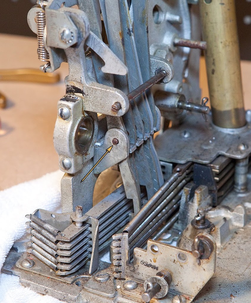
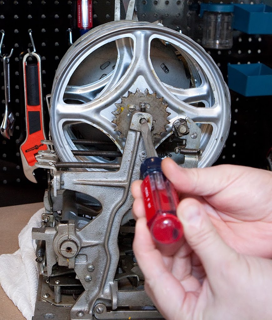
Back to the pushback lever assembly, it’s a pretty simple thing to remove but some caution is in order. The slot in the threaded shaft is very small, and you need a screwdriver that will fit all the way in the slot before you attempt to unscrew it. This shaft and the next one we will tackle have a tendency to stick, and if you aren’t careful you can break them fairly easily. I’d recommend that you not use an electric screwdriver for any slot machine disassembly tasks, but that goes double for these shafts. If the shaft gives you trouble, you may want to use some sort of penetrating oil to loosen it up, or in a pinch you can actually grab the center of the shaft with a pair of vise-grips and turn it a quarter-turn at a time to loosen it up if necessary.
Anyway, carefully unscrew the shaft and remove the pushback lever assembly.

It’s not a bad idea to replace the shaft after you’ve removed the part, but you might want to hold off for just a few minutes since it can get in the way when we remove the vertical payout fingers. I didn’t take that advice, and it caused me to miss something important. More on that in a minute.
The process for removing the vertical fingers starts at the top.
Before we go any further, remove the springs from the top of the fingers and store them in your spring jar. I’m planning to replace a good many of these anyway, but you never know when you are going to need an extra spring. (That’s called foreshadowing for those of you who failed Freshman English.)
The removal of the vertical payout fingers is a little involved. They are secured by a screw-in shaft like the part we just removed, although this shaft sometimes also has a lock nut on the back of it. Check for that before trying to unscrew the shaft. The same cautions apply for this shaft… it’s easy to damage.
Anyway, once you have the shaft removed, the payout fingers can be lifted out almost straight up, except for one thing.

Yup, while I was worrying about getting the fingers around that first shaft that I’d already replaced, I didn’t notice that there was a spring attached at the bottom of the front finger. This spring isn’t always present, and I just plain forgot about it. As you can see, I pretty much destroyed the spring.
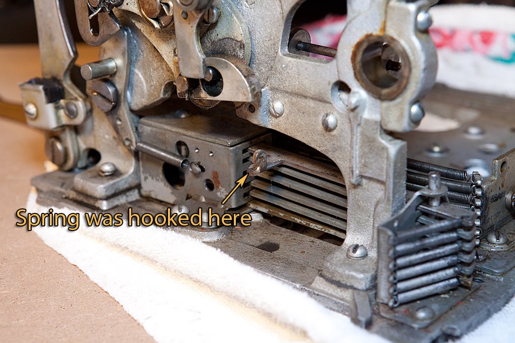
Luckily this isn’t a big deal, and I probably have a spare, but I’m still irked at myself for missing it.
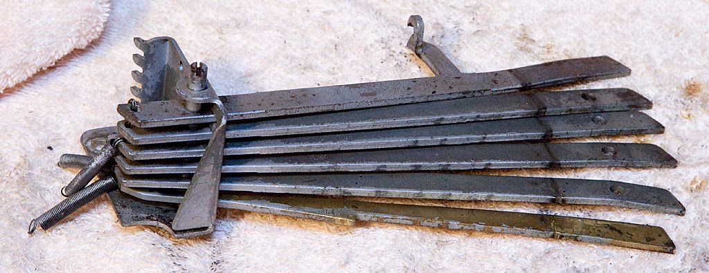
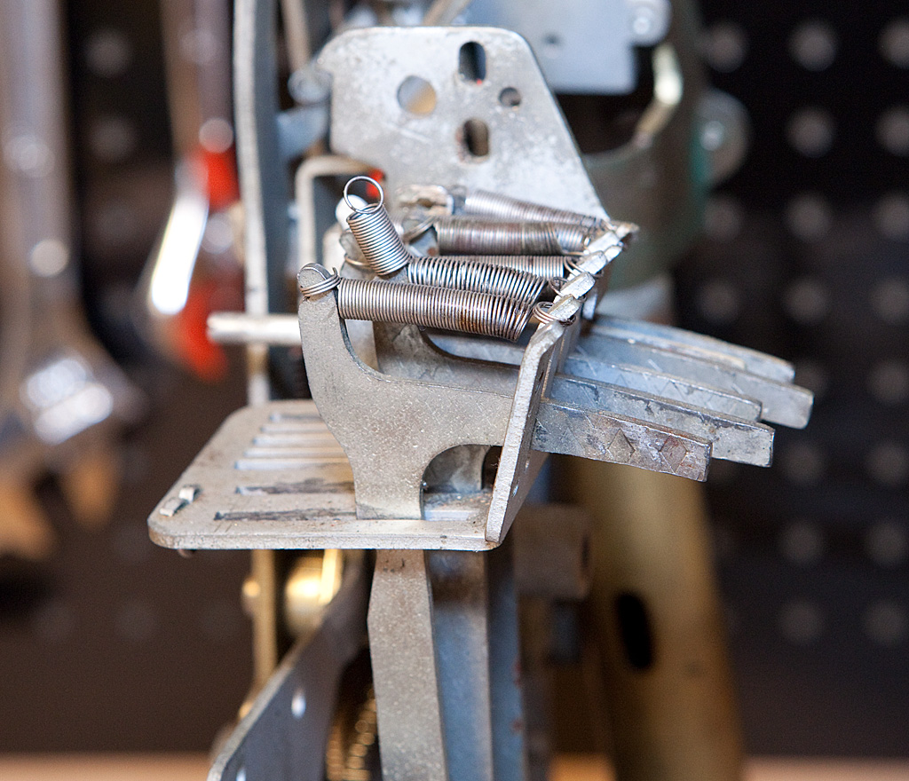
Enough with the spilled milk, though… let’s take a closer look at the vertical fingers.
Take a look at the photo of the fingers out of the machine above and notice that I’ve threaded some wire through them to keep them in the same order they were in on the machine. This is another good habit to cultivate. If you happen to forget, however, the order is generally easy to determine if you look at the bottom of the fingers.
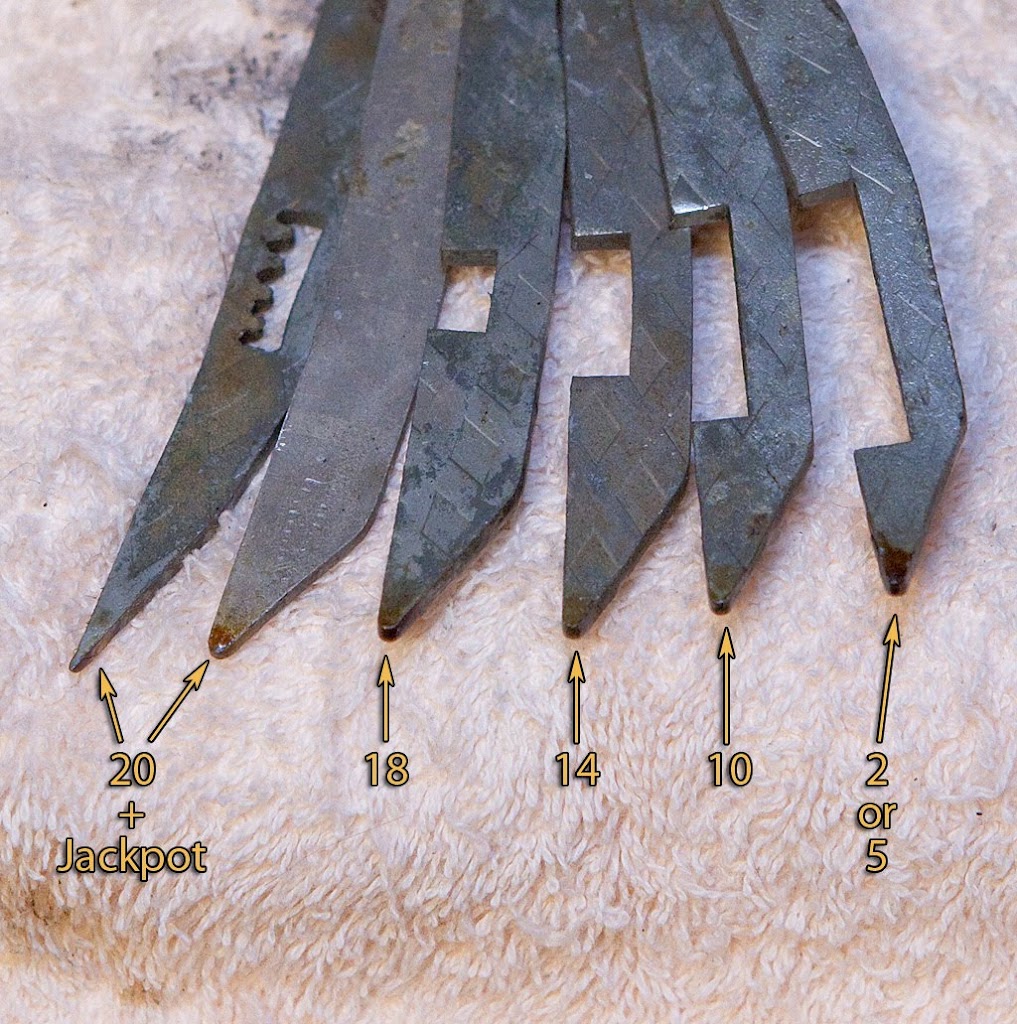
If you look at the notches above (not counting the saw-tooth stuff on the far left… that’s just for hooking the problematic spring) you can see that the notches get smaller as you go left towards the front of the machine. The actual “working” part of the vertical fingers is the spot just below those notches. Notice that it gets bigger as you travel to the left. This part of the fingers strikes the horizontal levers, which in turn release the payout slides. The more slides that are released, the bigger the payoff.
The fingers above correspond to the symbols for bars, melons, bells, plums, oranges and cherries respectively. If you look at the two far-left fingers, you can see that there is no notch at all, meaning that when activated these fingers hit ALL six of the horizontal levers, causing ALL six of the coin slides to travel backwards and drop their contents, including the very top slide which also trips the jackpot mechanism.If you total up the coins in all six slides, you end up with 20 quarters although this varies from machine to machine.
The finger for bells triggers five slides for 18 coins, the plum finger triggers four slides for 14 coins, the orange finger triggers three slides for 10 coins… but then we come to the cherries finger, which has two different possible payoffs.
The cherries finger is a special case, and can actually have two different states based upon how far it travels. If it moves just a little bit, as it does when there is a single cherry on the first reel but no cherry on the second reel, only the very bottom horizontal lever is triggered for a payout of 2 coins. The bottom horizontal lever has a special extension (which we will see later) for this exact purpose. When the finger finds a cherry on both the first and second reels, though, it travels far enough that it trips both the first and second horizontal levers, giving us a payout of 5 coins.
Based upon the above, we can also figure out how many coins each payout slide holds based upon the payoffs of the machine. From top to bottom, here are the coin capacities of the six payout slides:
2 — three bars or melons
4 — three bells
4 — three plums
5 — three orange
3 — two cherries
2 — one cherry
Pick any winning combination above, then add up the coins listed to the left of it plus all coins listed below it and you should end up with the correct payout totals, not counting the jackpot of course.
If this doesn’t make sense to you now, don’t worry about it too much. We’ll be taking a closer look at both the horizontal fingers and the payout slides later. The important thing to remember is that if you don’t keep the vertical fingers and payout slides in the proper order your machine will pay the wrong number of coins for winning combinations.
For now, let’s remove the vertical finger guide assembly.
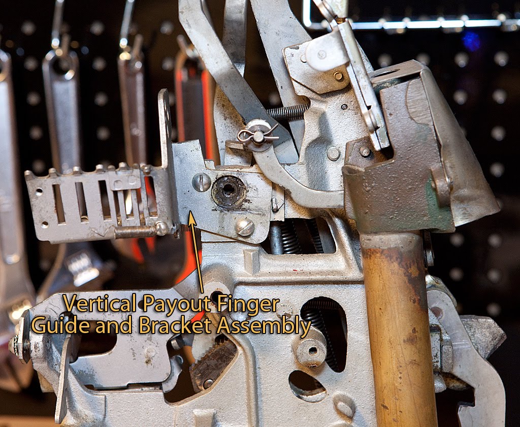
We’ve just got a couple of screws to remove, and then the guide should be hanging by a spring.
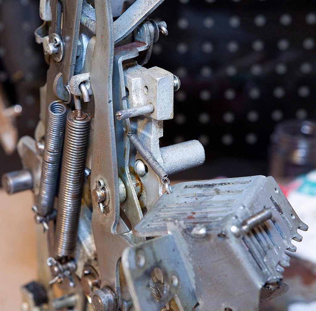
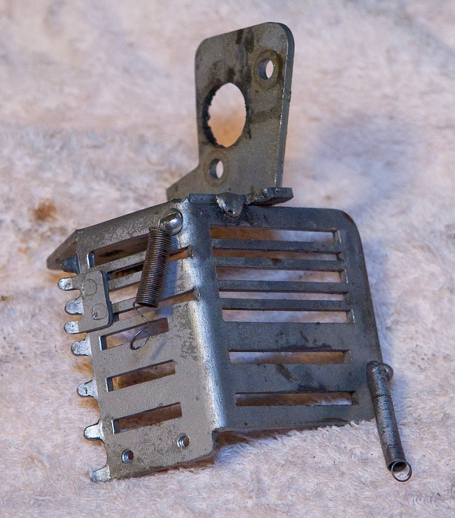
You’ll have to detach one end of the spring, but it doesn’t really matter which one. Here’s the finger guide by itself after removal, along with more errant grey paint.
We could have just as easily removed the finger guide before removing the fingers themselves, and that might well have been easier. When completely disassembling a mechanism, the order of parts removed just isn’t that critical.
That was some of the more complicate disassembly that we’ve done so far. Next we’ll tackle a few easy things.
The next part we’re going to remove is a small linkage lever that runs between the clock and the reel stop timing lever.
The lever is held on with two cotter pins, so no big deal to get it off the mech.

Next we’re going after the reel timing lever itself.

The reel timing lever is the part responsible for slowly allowing each reel stop lever to come in contact with its related star wheel, stopping the reels in a 1-2-3 order as the clock unwinds. It’s secured by a cotter pin and an attached extension screw.
The extension spring must also be removed at this time because it attaches to two ears and isn’t locked into a hole, so if we don’t remove it now we might lose it. More such springs are on the way, so we need to be sure that we have a box or jar in which to store all the stray springs.
Now, we move on to the clock assembly itself.
Earlier we referred to the main operating fork as the “spine” of the slot machine mechanism. If the operating fork is the spine, the clock assembly is the heart. If the clock stops, the machine stops.
Removal of the clock is accomplished by removing four screws that secure it to the base plate. Please note that these screws are located directly on the base plate. You don’t want to unscrew the wrong screws here and have the clock come apart. On this particular mech, the front two screws (right in the above photo) don’t even need to be removed since they are in slots rather than holes. Loosening these two screws and removing the two in the back of the mech should allow the clock to slide free.

The clock mechanism is pretty dirty, and we may well have to disassemble it and clean each part individually, but I’m hoping that a dip in some solvent and a re-oiling may be sufficient. Time will tell, I suppose.
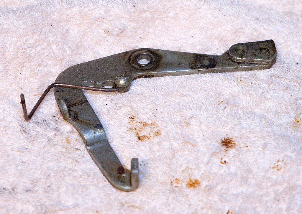
Next, we’re going to remove the payout slide lock lever. It’s secured with a single cotter pin.
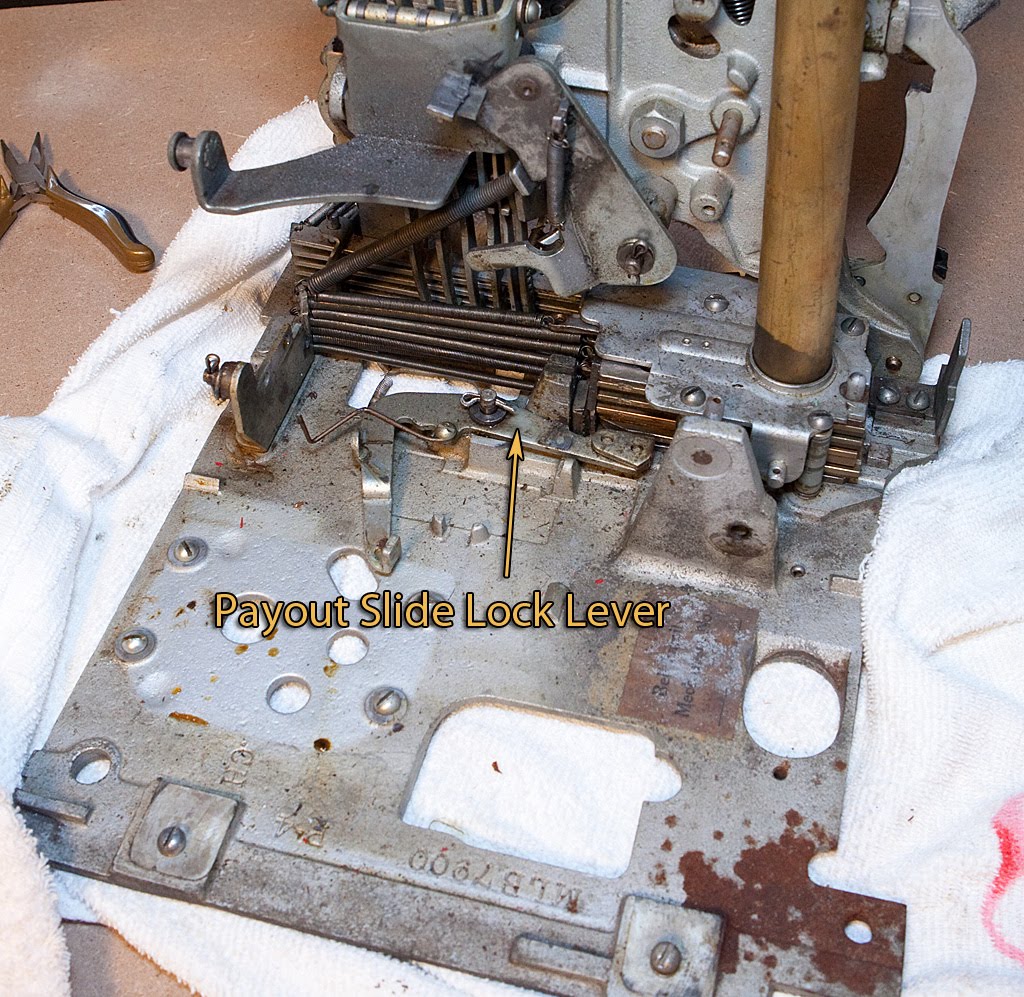
This lever holds the payout slides in place until all the reels have been stopped, the payout fingers have been released and the horizontal payout levers have been tripped (if applicable). This lever being activated essentially marks the end (or at least the beginning of the end) of the mech’s cycle.
Now it’s time to remove the kicker assembly. It may have been hard to locate in earlier photos, but you shouldn’t have any trouble now.
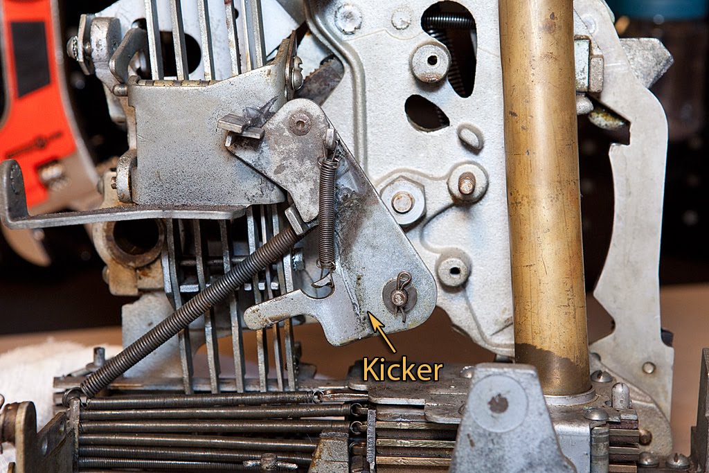
The kicker is attached by a single cotter pin and a long extension spring, so it’s easy to remove. Before we do that, take a look at the photo above. That long extension spring provides the direct power that spins the reels by pulling the kicker as it presses against the underside of the payout discs, kicking them into rotation. The second spring that is integral to the assembly pulls the top portion of the assembly out of the way after it kicks the reels, allowing them to spin without running into the kicker itself.
As you will recall, one of the initial problems I had with this machine was that the reels weren’t spinning. The problem that caused that condition was that the top part of the kicker was gummed up with a bunch of hardened grease, oil and dirt. Since the top part didn’t want to rotate, after the reel discs started spinning they were running into the kicker, which was stopping them again and causing the machine to make a “Clang!” sound as the reel disks were struck like a gong. It’s a common problem, and nothing that a good thorough cleaning won’t fix.
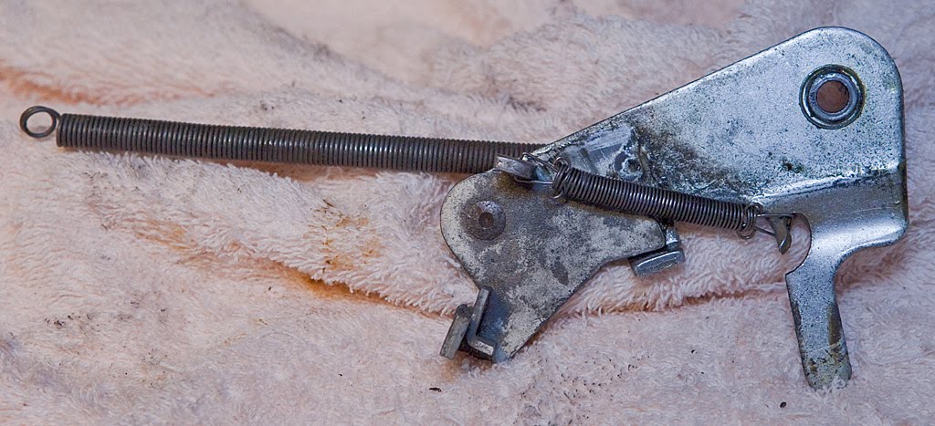
Here’s the kicker out of the mech:
Onward and upward… next time we’ll tackle the payout fingers and some of the related parts.
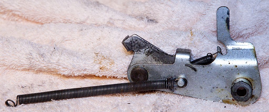
The next part of our antique slot machine restoration is the removal of the timing lever, pictured below.
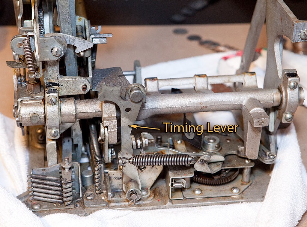
The timing lever’s job is to trigger the vertical payout fingers so that they travel forward and detect any winning combinations on the reels at the end of the mech’s cycle. It’s held in place by a cotter pin and a spring that is attached to a lever on the clock assembly. Removal is pretty much self-evident.
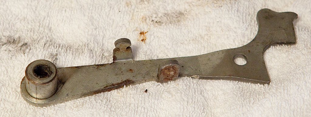
Next up (or more appropriately off) is the timing lever link assembly. Take a look:
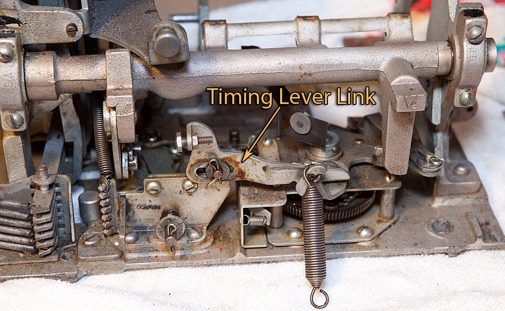
The timing lever link assembly provides an interface between the timing lever (that we just removed) and the clock assembly. On later Mills machines (like this one) there is an adjustment screw that allows you to vary the timing of the payout fingers’ release. Optimally, the fingers will release halfway between the stop of the third reel and the point at which the payout slides are released. Anyway, to remove the timing lever link assembly, remove the cotter pin under the adjustment screw on the left of the part, then swing the part out to get to the other cotter pin pictured below.

I’d recommend leaving the adjustment screw in place for now, particularly if your machine was in generally working condition when you started disassembly.
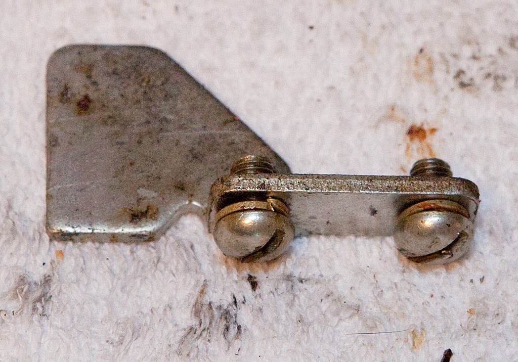
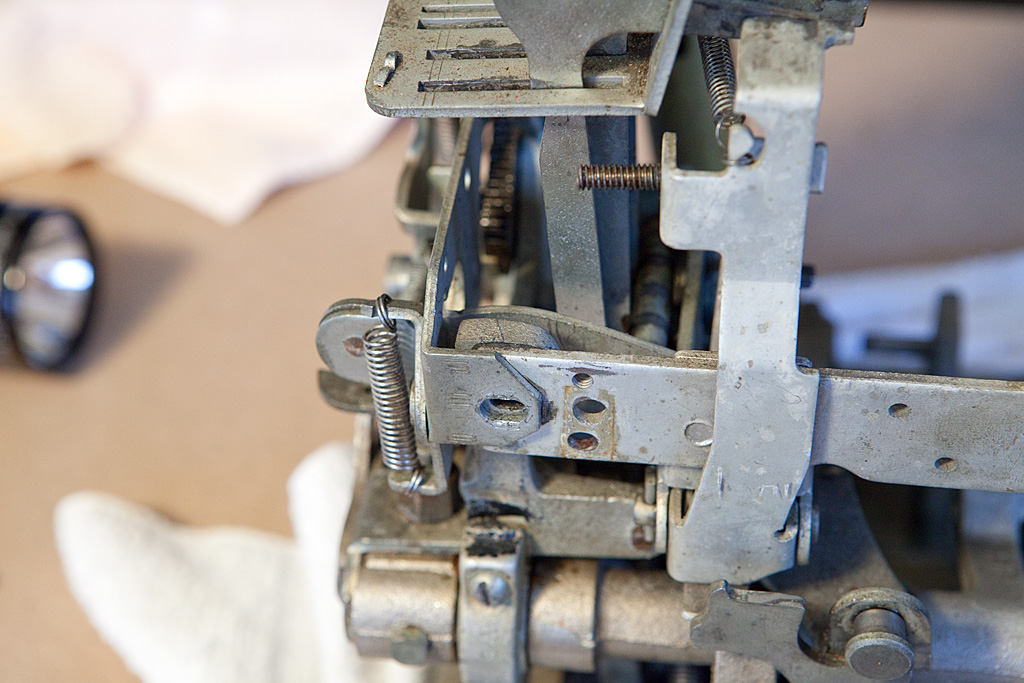
There’s one last part we’re going to remove before taking out the main operating fork, and it’s a little hard to see. It’s a small bracket on the back of the timing lever bracket and stud assembly. It is secured with two screws, as seen in the photo below.
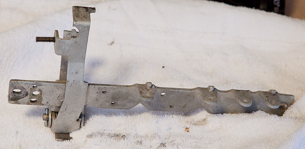
Remove those two screws and the bracket will drop and you’ll have to fish it out of the mech. It looks like this once removed (with the screws replaced, of course):
With that part out of the way, we are free to remove the main operating fork, which is somewhat like the spine of the slot machine. When the machine is cycled, virtually every part of the operating mechanism depends upon the main operating fork. Removal of the fork should be pretty easy now that we’ve removed so many parts. The fork is secured by four screws as shown in the two photos below.

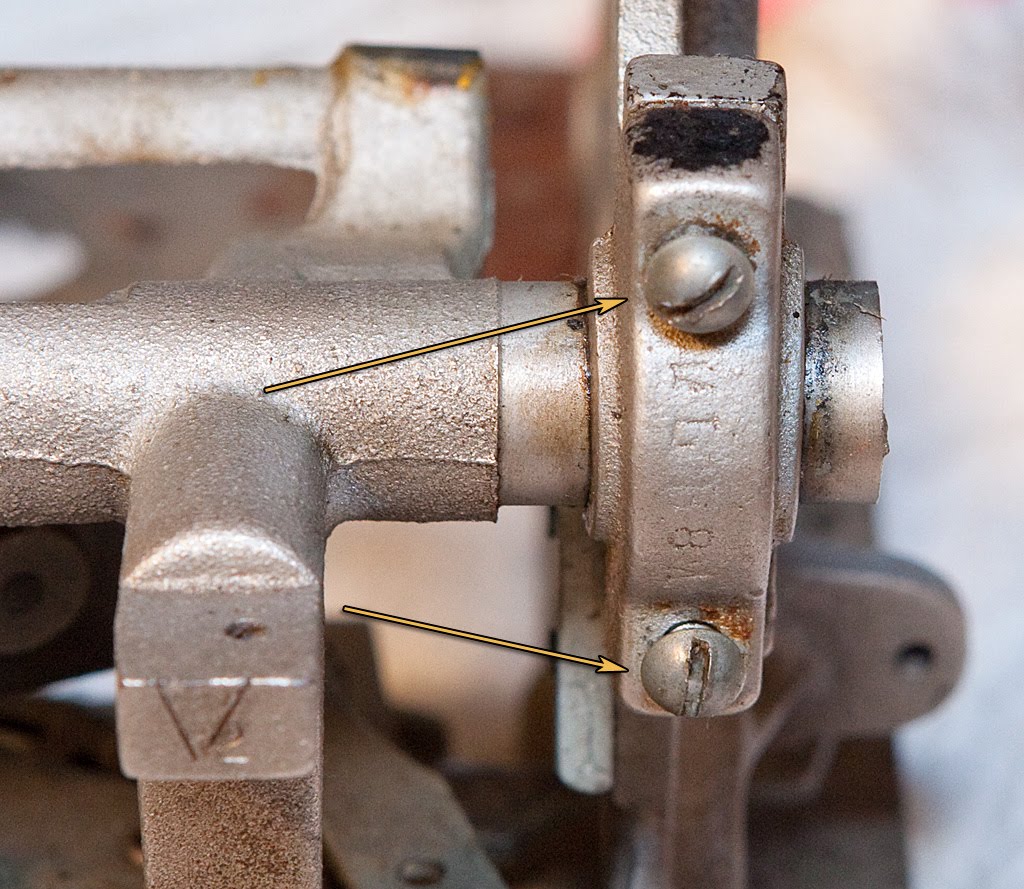
Each pair of these screws secures a removable portion of the main operating fork bearings. It’s important to note that these bearings should be replaced exactly as they were removed, meaning that you should keep the right one on the right and the left one on the left. You should also keep them aligned the same top-to-bottom, so be sure to keep them straight and replace them immediately after you remove the main operating fork assembly. Here’s what the fork assembly looks like after removal:
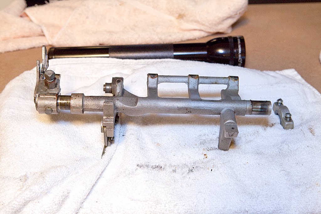
As before when we removed the rear bracket, we’re not going to attempt further disassembly of the main operating fork assembly at this time. We’ll tackle that later during cleaning. By the way, notice the grey paint on the spring above. That’s a sure sign of someone taking bad shortcuts.
The mechanism certainly looks different now… let’s take a look.
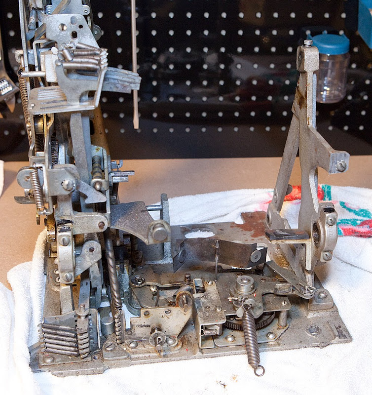
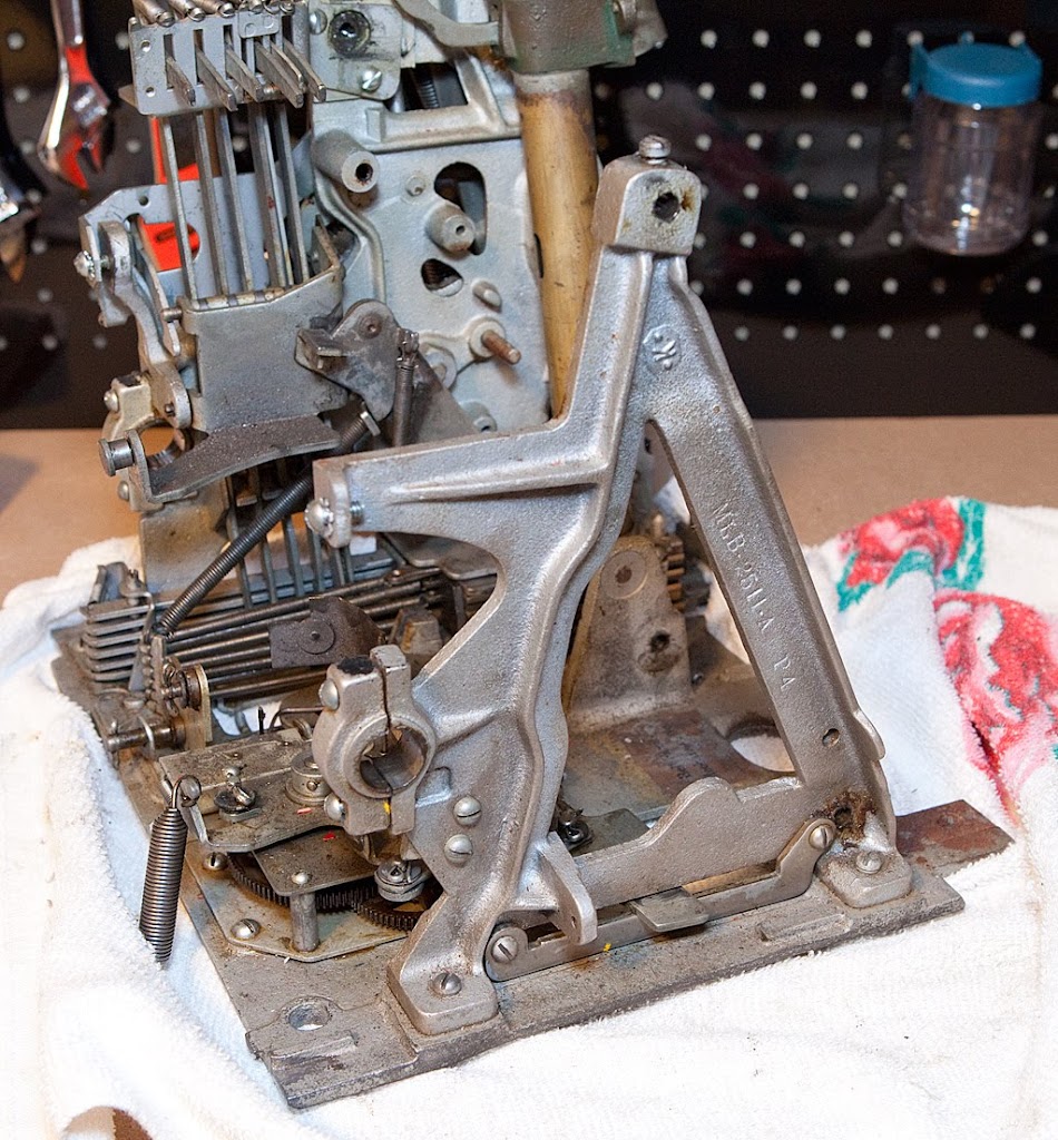
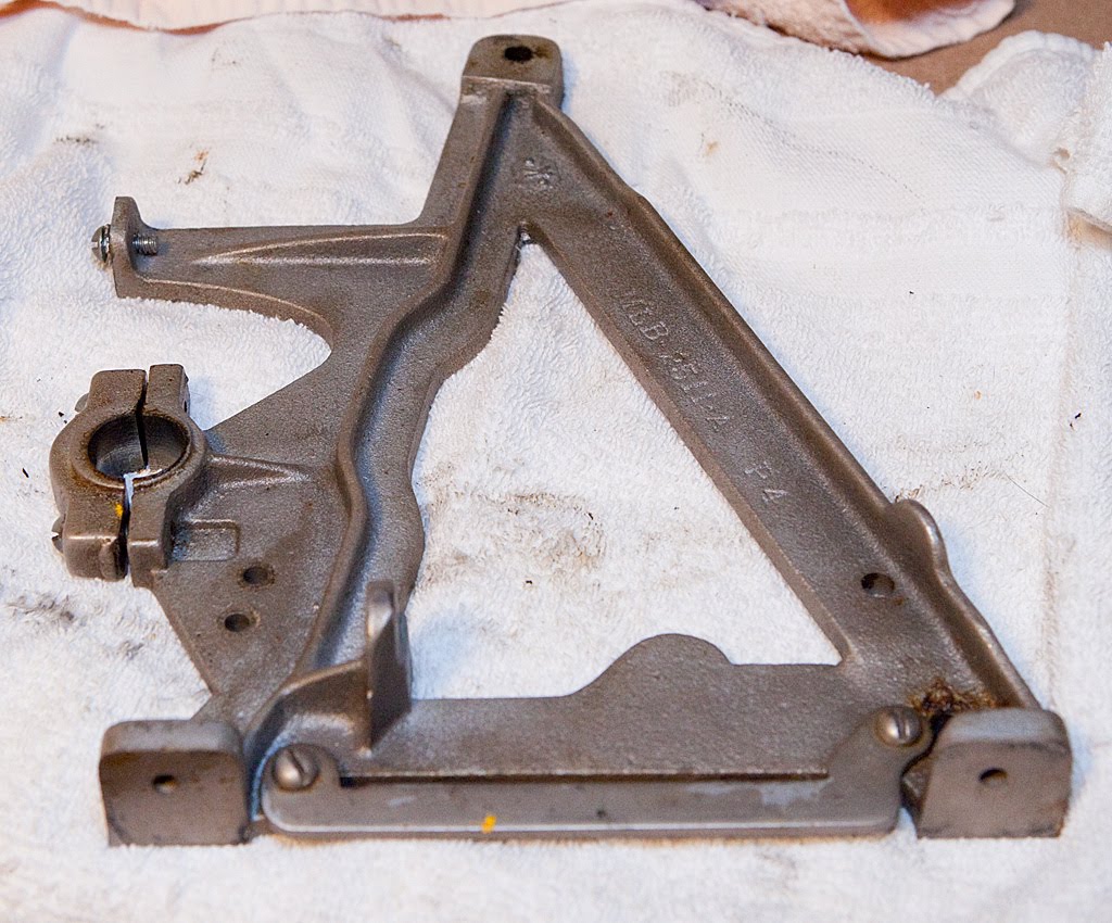
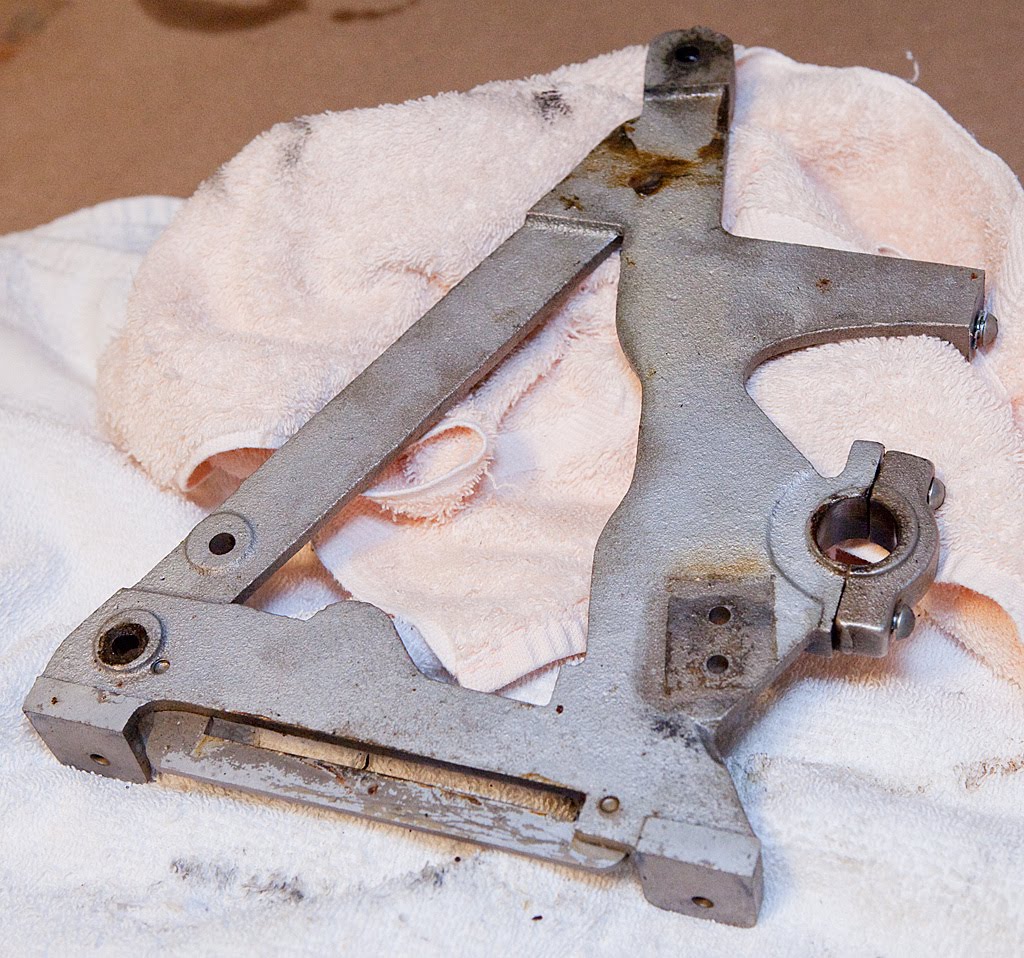
The A-frame pictured above should come off easily now just by unscrewing the two screws that attach it to the base plate, but there’s a small part that I’m going to remove first.
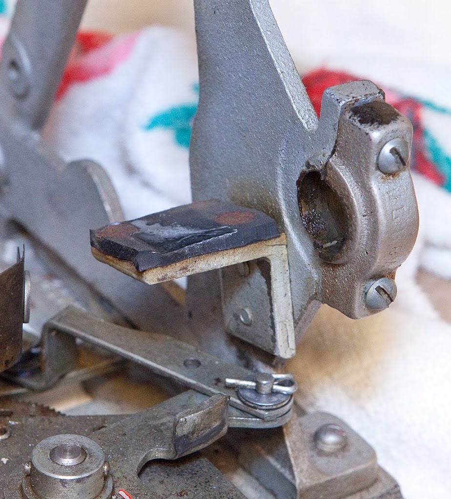
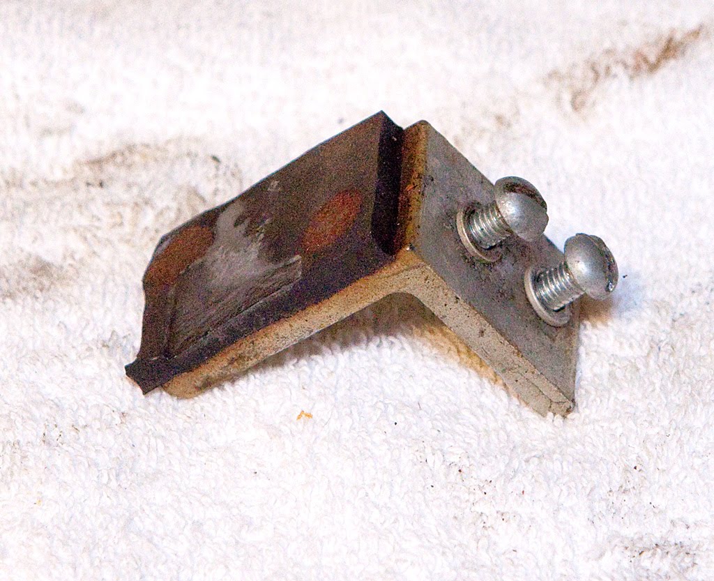
This part is called the felt pad bracket and assembly, but it sure doesn’t look like there’s any felt on this one. Removing it is a snap, just undo the two screws securing it to the A-frame, then remove the A-frame itself from the base plate.
Before we move on, let’s take another look at what’s left of the mechanism.
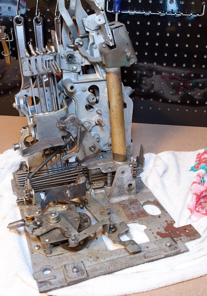
It definitely looks different. Here’s a closeup of the clock mechanism:
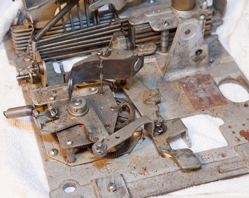
If you’ve never taken a machine completely apart before, take some time now and play with the different parts you see. Take note of how they operate and it will greatly enhance your understanding of how a mechanical slot machine operates.
With the reel bundle gone, we can begin the tear-down in earnest. Let’s take a look.
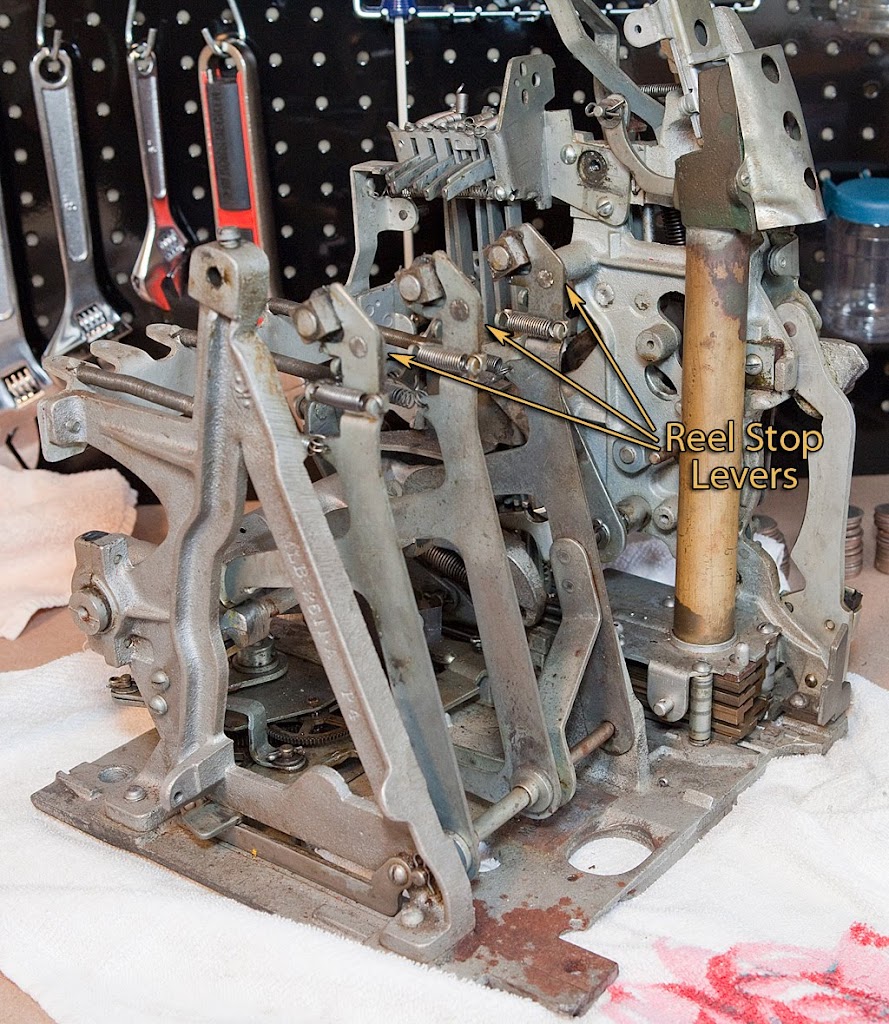
We’ll start with the reel stop levers. We need to get the levers out of the way, then remove them. The first step is to disconnect the reel stop lever springs. The springs are easy to find… they are the long springs attached to each of the reel stop levers that connect them to the back of the mechanism. As with most springs in the machine, one end will be threaded through a hole and the other end will be looped around some sort of post or ear. Generally it is a good idea to slip the spring off of the ear and leave it connected to the part where it is threaded through a hole.
After the springs are disconnected from the back bracket, you can lay the reel stop levers down as shown above. Now we need to remove the levers themselves by removing the shaft at the bottom of the levers. This is a pretty simple matter, although the shaft is sometimes difficult to remove due to the accumulation of dirt and hardened oil/grease.
Depending on the machine, this shaft is usually held in place by two hairpins or cotter pins. (Regional note: I’ve noticed that people in the South tend to use the term “cotter pin” while folks in the Midwest and Northeast tend to say “cotter key”. Either way, they are the same thing.) On this particular slot machine, the shaft is held by hairpins. We only need to remove the pin pictured above, which is easily accomplished with a pair of needle nosed pliers. Be careful when removing this sort of pin since they have a tendency to shoot across the room and get lost forever if you don’t have a good grip.
With the other pin removed, take a small pair of vice grip pliers and lock them on the end of the shaft protruding from the A-frame as pictured above. The shaft should slide straight out, although you will probably have to turn it back and forth and possibly move the reel stop levers as you are pulling.
Once the shaft has been removed, put the other hair pin back in place and store the shaft for future cleaning. As with screws, it’s good practice to put pins back in place before proceeding on.
The photo above shows what the three reel stop levers look like once they have been removed. I’m going to leave the springs attached for now just to keep up with them. Note that the three levers are not identical. The one on the right (as you are looking at the front of the mechanism) has an offset and two holes where the shaft goes through the lever. The other two levers are held apart by a separate, tubular spacer that also goes on the shaft.
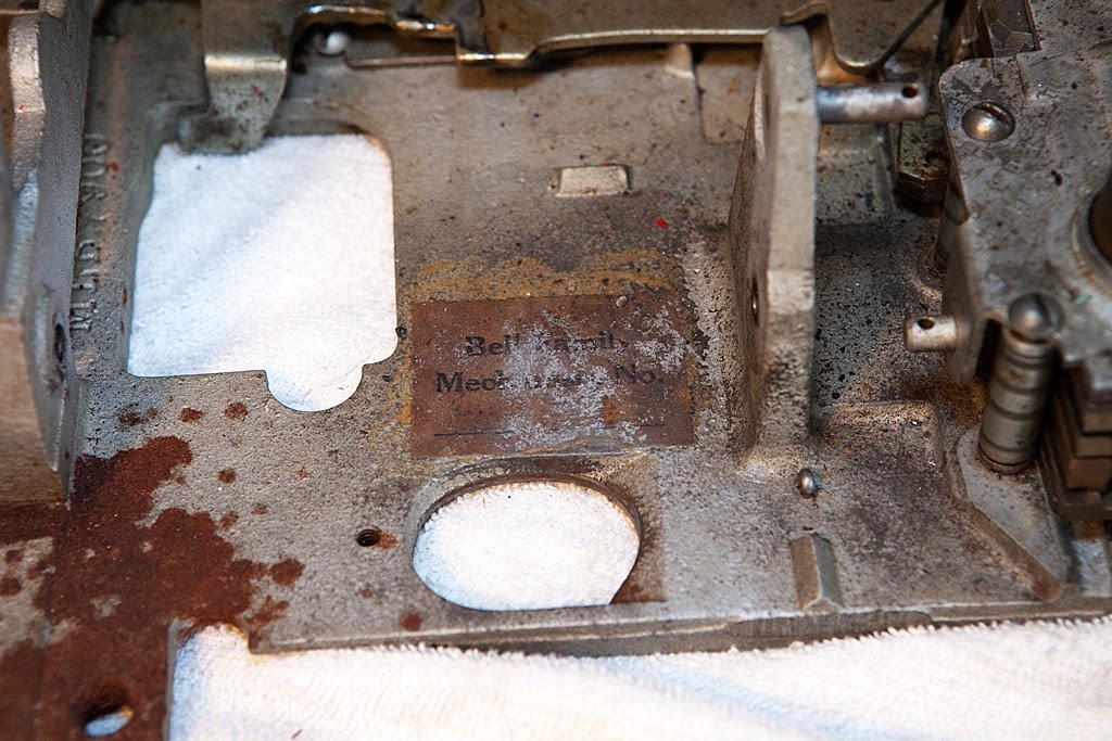
With the reel stop levers and shaft gone, we have a much clearer view of the base plate. Let’s take a close look at the label.
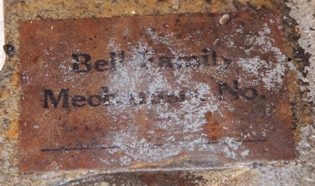
Unfortunately I don’t think we’re going to be able to read the serial number through all of the dirt, oil and paint. I’ll still save the label, but I really wish the serial number was readable. Oh, well… you can’t win them all.
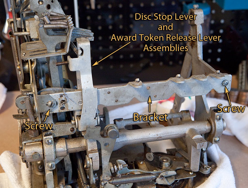
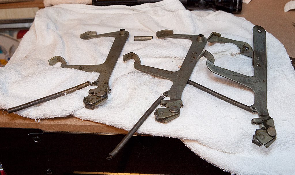
The next part we’re going to remove is the rear bracket that holds the reel brakes (if present) and the disc stop lever. It also holds the award token release lever on machines that are equipped for a gold award token dispenser. Removal is pretty straightforward since the bracket is only held on by a couple of screws. We’ll also have to disconnect a spring from the award token release lever. Before we go on, however, there’s a situation we should discuss. Let’s take a look.
As you can see in the photo above, there is a paperclip bent around the bracket, keeping a hooked part behind the bracket stationary. Why in the world would someone do this to a slot machine? The answer is pretty simple, and this sort of “fix” is relatively common on antique Mills slot machines. The part behind the bracket is the anti-check payout hook, and its purpose is to keep the slot machine from paying out coins if someone has played a “check” instead of a coin. Checks look a lot like washers, having a hole in the middle, and were used in some locales to get around anti-gambling laws. We’ll look at this part in more detail later, but for now let me just say that this part is unnecessary for a home machine, and generally a pain to work with. The anti-check assembly has a tendency to freeze up or get sluggish, which can keep the machine from paying out correctly or at all. Some people remove this part completely, and others use a “fix” similar to the one above using bailing wire or a zip tie. For now we’ll just remove the paperclip and the other things securing the back bracket.
The photo above shows the left side of the bracket after the screw and paperclip have been removed. Note how the bracket fits in between the various parts… this will be important during reassembly.
Here’s what the bracket looks like after removal. Notice that the disc stop lever and the award token release levers are still attached. We’ll remove these later when we clean this part and put them back in place before moving on. I prefer working on parts and assemblies using this sort of “modular” approach rather than disassembling absolutely everything at one time. It keeps parts together and helps you get a feel for how parts interact on the machine.

Here’s another view of the bracket and related parts. You can clearly see the disc stop lever in the foreground. This part keeps the reels from spinning backwards while the mechanism is being cocked.
Next time we’ll tackle the main operating fork and related parts.
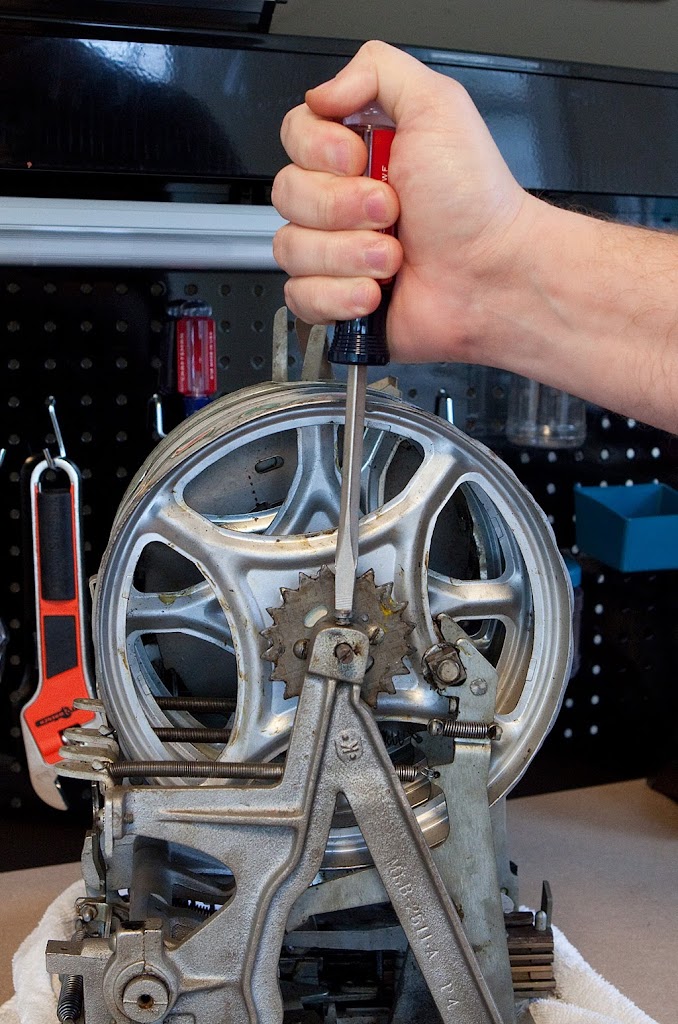
Now we’re ready to take the reel bundle out of the machine. The first thing we need to do is cycle the mechanism. You can pull the handle (or screwdriver) down all the way and stop the clock if you want, but it is sometimes easier to pull it down almost all the way and leave the mechanism in a partially-cocked state. We’re just trying to get the reel stop levers to pull away from the star wheels and have the payout fingers pulled away from the discs. Once you do this a couple of times you will get the hang of it. If you have done it correctly the reels will be able to spin freely. At this point we need to loosen the reel shaft retaining screw.
Notice that I said “loosen” and not “remove”. Although you can remove the screw entirely, it’s a bad habit and should be avoided. Screws are easy to misplace, and it will be much easier to reassemble the mechanism later if we keep all the screws in their proper place. In fact, even if you need to remove a screw as part of the disassembly process, it’s a good practice to replace the screw after you’ve removed the related part. Trust me on this one… you will thank me later. After we have the screw loosened, we can unscrew and remove the shaft itself.
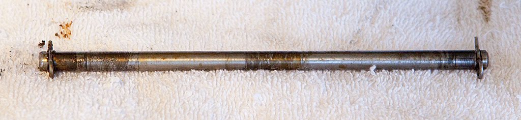
You may want to support the reel bundle with your free hand while you are unscrewing the shaft, just to keep it from slipping down as the shaft comes loose from the other side of the mech. After the shaft has been completely unscrewed, grab the end of it and pull. It should slide right out. Here’s what it looks like once it’s been removed.
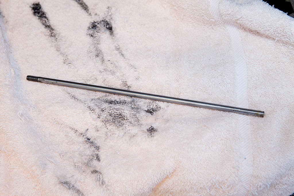
It isn’t much to look at, and it’s pretty much guaranteed to be covered in oil and dirt. There’s really only one part of the slot machine to which oil or dirt can do permanent and irreversible damage, and that’s the reel strips. If you are trying to save your strips, you need to be extra careful not to get them dirty, so a good hand cleaning may be in order before you go any further. We’re going to be handling the reel tins (the part of the mechanism that holds the reel strips) as we remove the reel bundle, which brings us to another law of slot machine restoration: Reel tins are vampires. They want your blood. If you spend any amount of time working on an antique slot machine, you are going to end up cutting yourself on one of the reel tins. They are made of sheet metal and their edges are very sharp. Blood isn’t any better for reel strips than dirt or oil, so be careful. A Tetanus shot is probably not a bad idea either… I always keep mine current. Anyway, the process of removing the bundle is hard to photograph, so I’m just going to describe it. Essentially, you hold the bundle and lift it pretty much straight up, maneuvering the reel tins around the reel stop levers. Both the reel stop levers and the reel tins have a bit of “play” in them, so it shouldn’t be too hard. Here’s what the reel bundle looks like once it is removed from the mech:
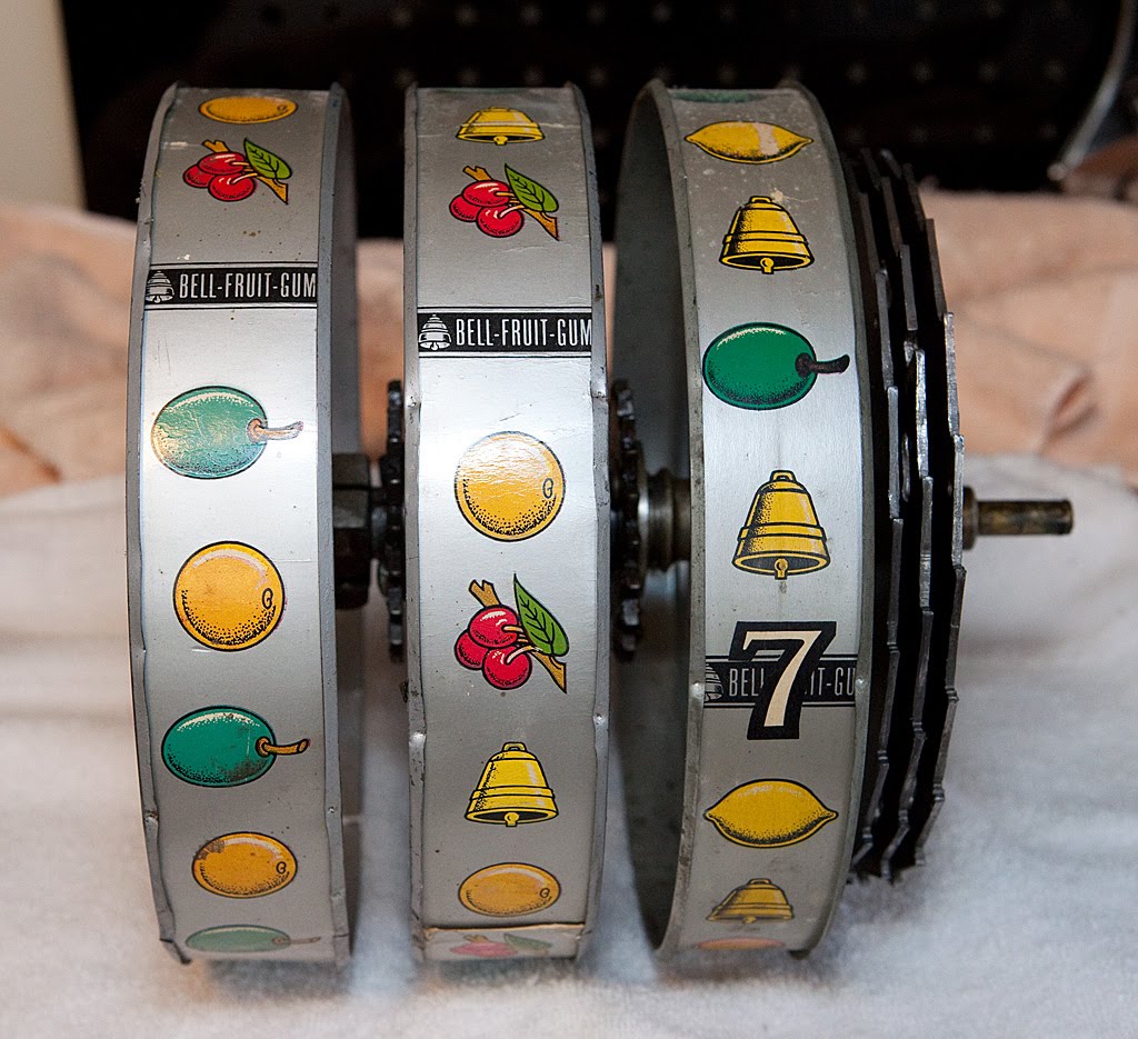
Outside of the mech, it’s easier to see how the bundle functions. Turning the left-most reel causes the right-most reel disc to turn. It seems backwards at first, but it makes sense when you remember where the payout fingers were located. Let’s take a look at it from a couple of other angles.
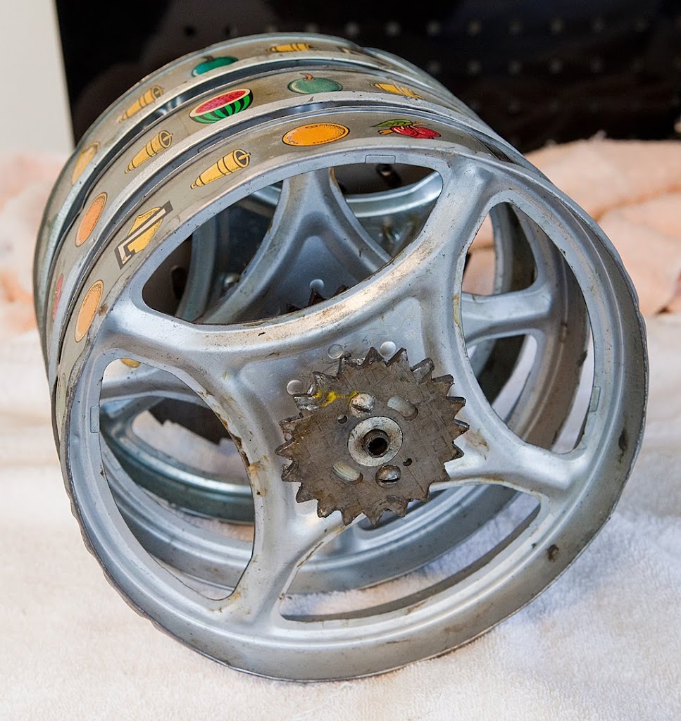
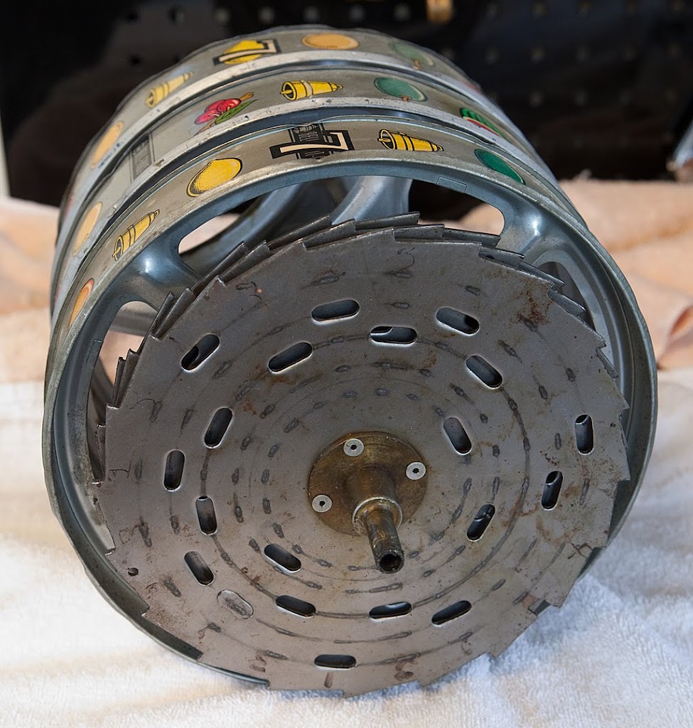
Here we can see the reel discs and all the various holes they contain. Each hole corresponds to a specific symbol on the corresponding reel strip. Let’s look at it dead on.
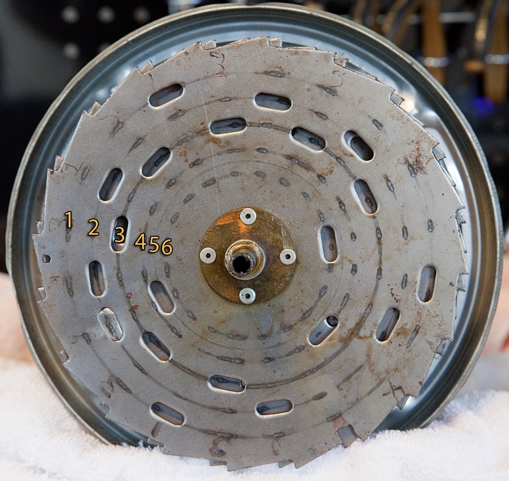
Look at the numbers above. They all represent the positions of the payout fingers for a particular spot on the corresponding reel. Since our Mills “21″ Bell has melons, there are six symbols that correspond to potential payoff combinations. In general, the closer you get to the center of the disc, the more valuable the symbols are. On our machine, the numbers above represent the symbols as follows:
1. Cherry
2. Orange
3. Plum
4. Bell
5. Melon
6. Bar
If we look at number 3 above, we see that there is a hole in the disc, meaning that a plum would be in the payout position if the reel stopped with that hole under the payout fingers. In addition to the other symbols listed above, the reels also have lemons, which generally don’t have any associated payoff so they don’t have any holes or a payout finger to detect them. Some Mills slot machines feature “Mystery Payoffs” which really aren’t any mystery at all if you look at the reel discs. Usually a mystery payoff is accomplished by having a hole punched in the orange position when a specific bar or melon is displayed, meaning that normally non-paying combinations like Melon-Orange-Orange or Bar-Orange-Orange would pay off. Likewise, on machines that feature a “Deuces Wild” theme, the reel discs have holes in all the symbol positions whenever a deuce is displayed, making it function as a wild card. If you recall from earlier entries, the “21″ Bell has a special award feature that awards a super-jackpot token when the player hits a 7-7-7 combination. Since the 7s are displayed on top of other symbols on the reels and there is no hole that corresponds to 7s, the token award payout is accomplished through a different means.
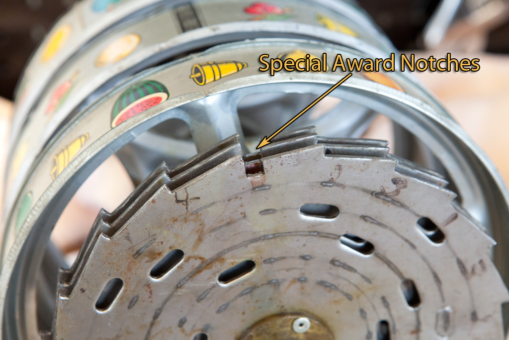
In the photo above you can see the special notches cut into the reel discs that correspond to a 7-7-7 combination. If we look at the front disc (which corresponds to left-most reel when looking from the front of the machine) and draw a line from the notch towards the center of the disc we see that no holes are punched for that particular position. This tells us that the 7 on the first reel shares its position with a lemon. Let’s see what the front of the mech looks like now that the reel bundle has been removed.
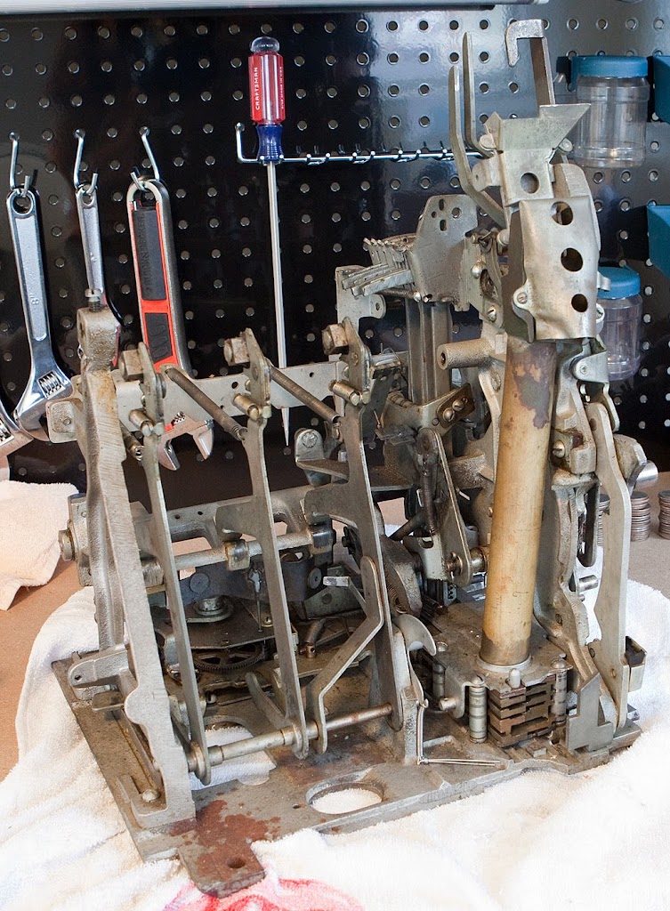
As you can see, everything is much more accessible now that the reels are out of the way. See if you can spot the kicker that we discussed earlier in the above photo. If not, don’t worry about it… we’ll get to it later. Before we move on, there are a couple of things we should do. First, we should put the reel bundle somewhere safe, particularly if we’re trying to save the reel strips. We’ll disassemble it later on, but we don’t need it now. Next, we should start filling a box with the parts that we’re going to clean and degrease. The reel shaft will be the first part to go into the box. Again, it’s very easy to misplace parts, so a little bit of caution is warranted. Last, it’s probably a good idea to get any remaining coins out of the mechanism. Assuming that the payout slides are working, the easiest way to do this is to cycle the mechanism a few times. Since the reel discs are not in place, there is nothing to stop the payout fingers from traveling all the way forward, making the mechanism think that we have hit every possible payout combination. As far as the machine is concerned, we hit a jackpot every time! After each spin, tip the mechanism up and remove the coins from underneath. It will probably take 7-8 cycles to empty the payout tube on most machines. That about does it for the reel bundle removal. Now the real fun begins.
Ok, enough with the books and theory… let’s start tearing this thing down.We’re going to be working with the mech out of the case from now until it is completely disassembled, cleaned, reassembled, repaired and adjusted.
First we’ve got to get the reel bundle out of the machine. This is relatively simple, but let’s take a look at the bundle and how it interacts with the rest of the machine.
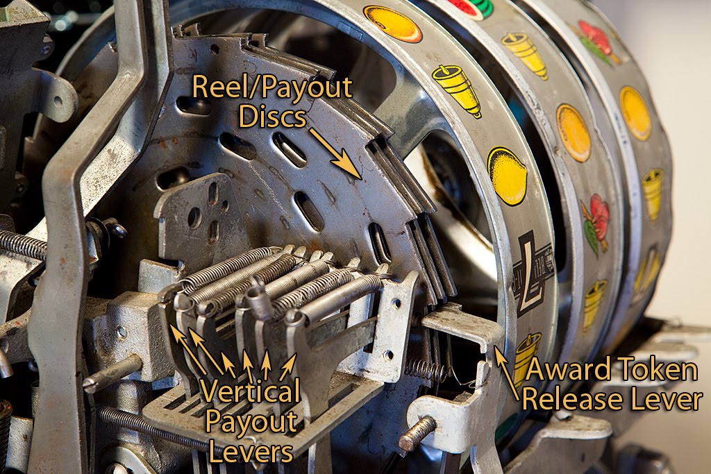
Some of this will be more obvious after we get the bundle away from the mechanism, but the above photo shows some critical parts of the payout mechanism. The reel discs tell the mechanism which symbols are showing in the payout window through a series of strategically placed holes. The vertical payout levers (sometimes called “payout fingers”) travel into these holes and transmit any winning combination mechanically to another portion of the payout mechanism called the horizontal payout levers (not pictured yet.) In turn, the horizontal levers determine which payout slides move into position, allowing coins to fall into money bowl.
Also pictured above is the award token release lever, which functions a bit differently from the payout fingers. This lever determines if the reels have lined up on 7-7-7 by sliding into a special notch on the outside of the reel discs. You can’t see the notches above, but once the reel bundle is away from the mech we’ll take another look.
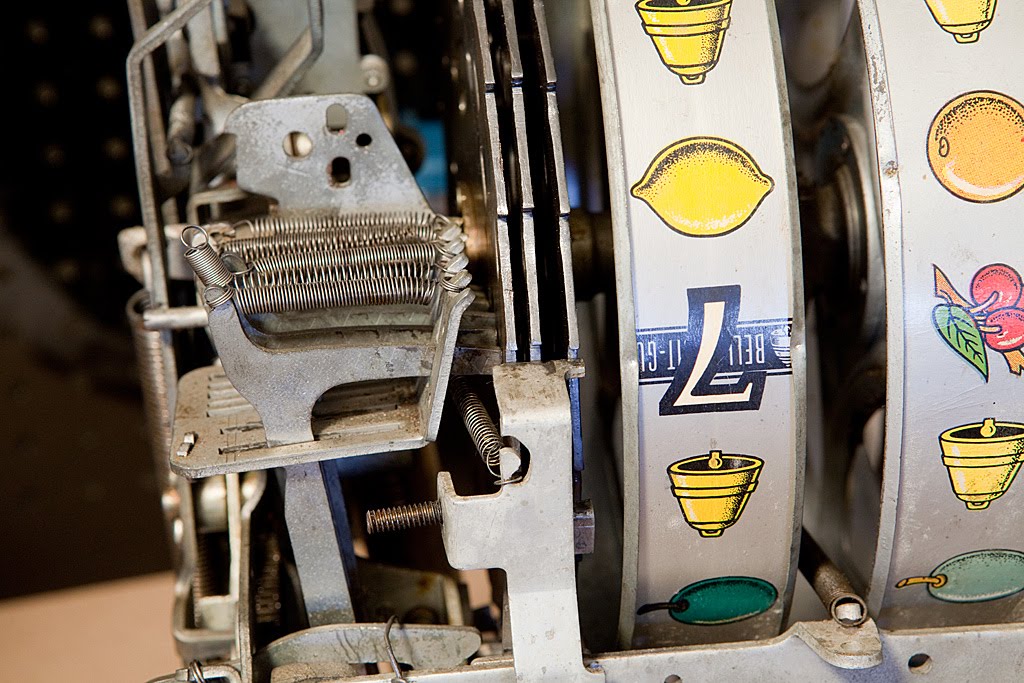
Here’s a rear view of the payout fingers and the award token release lever. Normally there would be a push bar assembly connected to the award token release lever on machines with the gold award feature, but that part is missing from this particular machine. We’ll worry about that later.
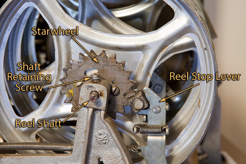
On the a-frame side of the reel bundle, we find a couple of parts that deal with the process of stopping the reels. Notice the starwheel and the reel stop lever. When the mechanism is cycled, each of the three reel stop levers move in turn to engage each reel’s starwheel, bringing the reels to a stop and ensuring that they stop with a symbol squarely in the payout window.
The two other parts pictured above are the reel shaft retaining screw and the reel shaft itself. In order to remove the reel bundle, we first loosen the retaining screw, then unscrew the shaft so that it can be pulled free. Be aware that other slot machine models may have a second retaining screw located at the other end of the shaft, and some models of machine have a reel shaft that is simply pulled out rather than unscrewed and then pulled free. Take a good look at the machine before attempting to remove anything.
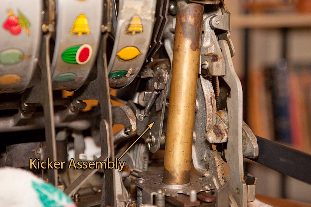
Finally, we’re going to look at the underside of the reel bundle as best we can while it is still in the mechanism. In the photo above you can see the kicker assembly, although it will be much easier to see once the reel bundle is removed. For the purposes of this photo, the mech has been partially cycled, leaving it in the “wound up” state. The kicker assembly engages the underside of the reel discs and imparts force to them once the reel stop levers have disengaged and the payout fingers have retracted away from the discs. This force is what actually causes the reels to spin, and this was one of the parts that was frozen up when I first acquired the Mills 21 Bell.
Tomorrow morning I’ll be removing the reel bundle and photographing it in more detail. If you are following along with your own machine and intend to do a full disassembly, you might want to pop the mechanism back into the case and play it a few times before proceeding. Once we start the next step it will be a while before the machine can be played again.