From this point forward, most of the disassembly of the slot machine mechanism is pretty straightforward and doesn’t need a lot of explanation. The order in which you remove parts usually isn’t critical; as long as you can get to the parts easily and remove the necessary screws and springs the part is probably safe to remove. By the time we finish this section we’ll have the entire right-hand frame removed from the mech. Let’s get started.
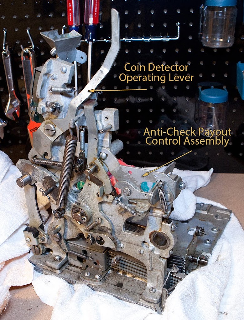
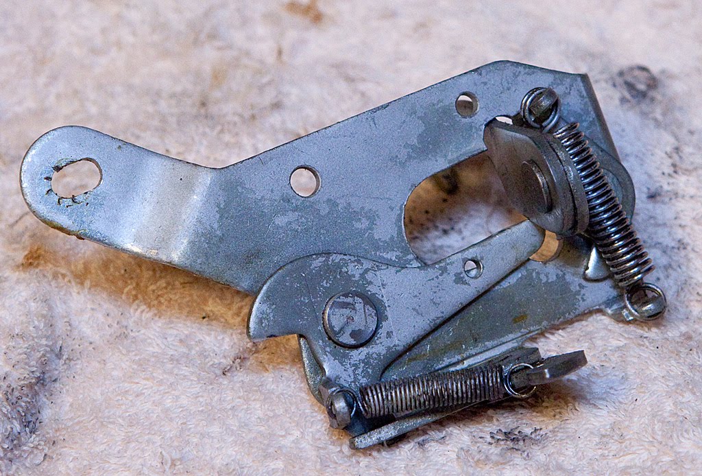
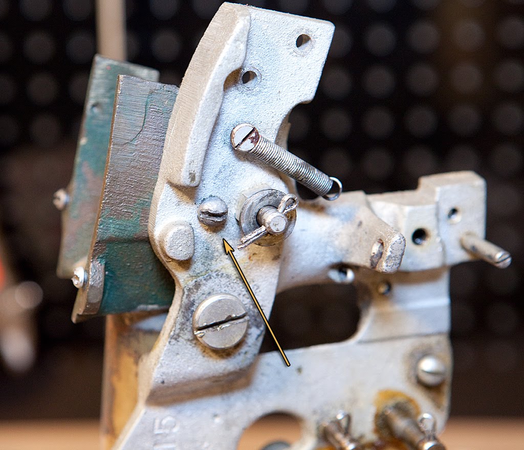
The two parts highlighted above are pretty easy to remove. The coin detector lever should be familiar to you from our earlier discussion regarding the operation of the mechanism outside of the cabinet. This lever interacts with the escalator to determine when a coin has been inserted, and in turn allows the mech to cycle. We’ve also discussed the anti-check payout control assembly at some length. Both should come off the mech easily at this point. The coin detector lever is held in place with a shoulder screw.
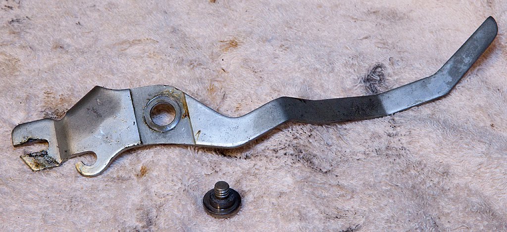
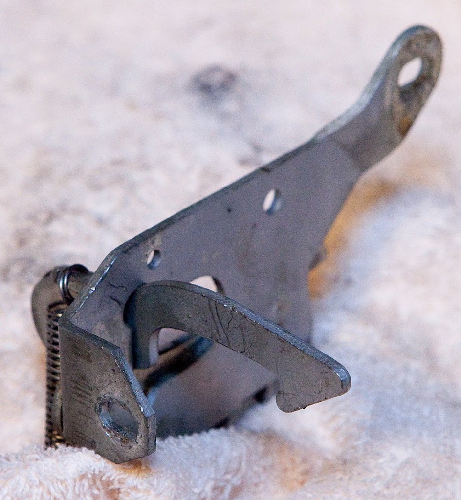
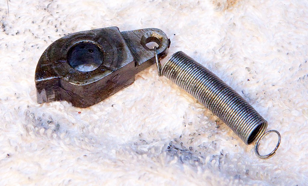
If you aren’t familiar with term “shoulder screw” this photo should make the concept clear:
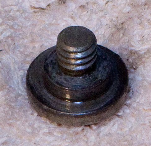
As you can see, the threads of the screw don’t extend all the way to the head, and there is a “shoulder” between the head and the threads. That shoulder is the surface upon which the lever rotates.
Back to the anti-check payout assembly, it is held in place by two screws: one at the back of the mech, and another on the side. They should be easy for you to locate.
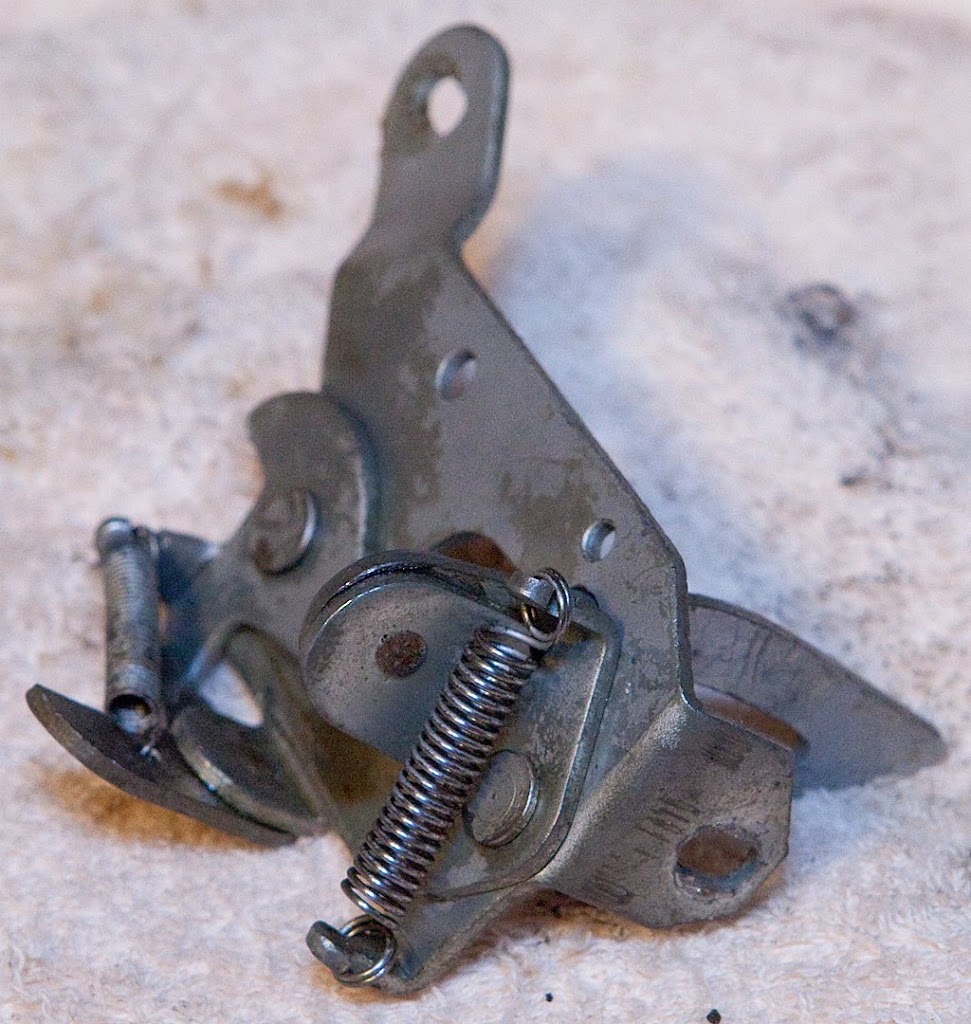
Once you have this assembly off the mech, be sure to play with it a bit to get a good idea of how it operates, particularly if you intend to reinstall it and leave it in working condition rather than applying the “fix” we discussed earlier.
Now let’s move on to the overflow pushbar assembly.
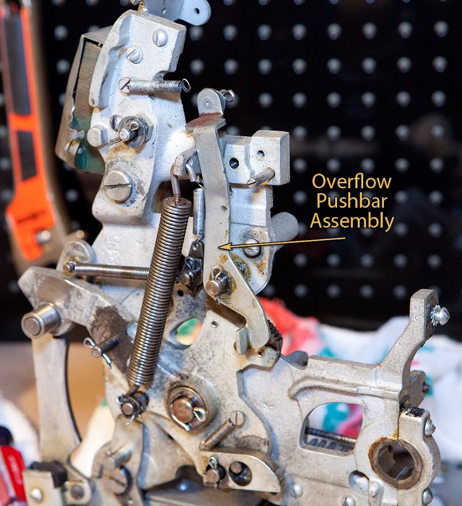
We’ve already removed the pushbar itself in an earlier step, but this is the lever that actually operates that pushbar which keeps the coin tube from overflowing by pushing coins into the jackpot assembly.

Moving right along, let’s look at the operating fork dog.
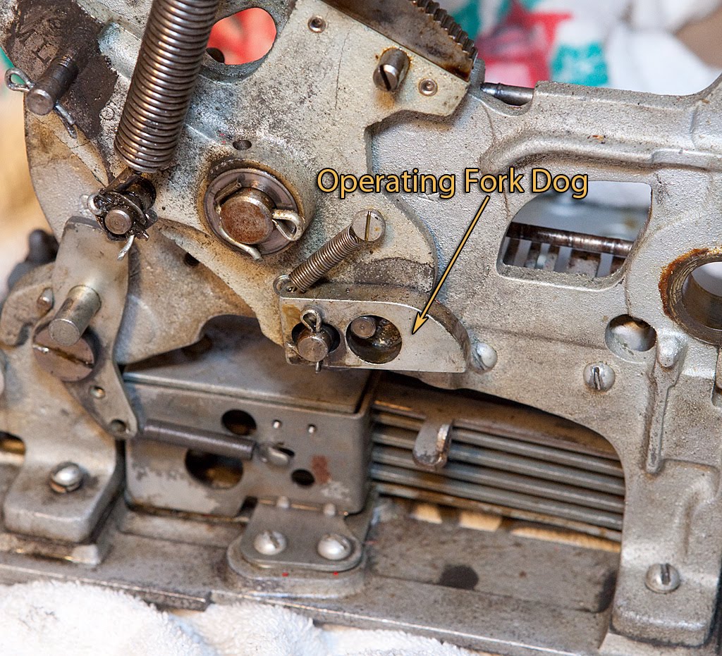
Removing the cotter pin and the related spring frees this up to be removed.
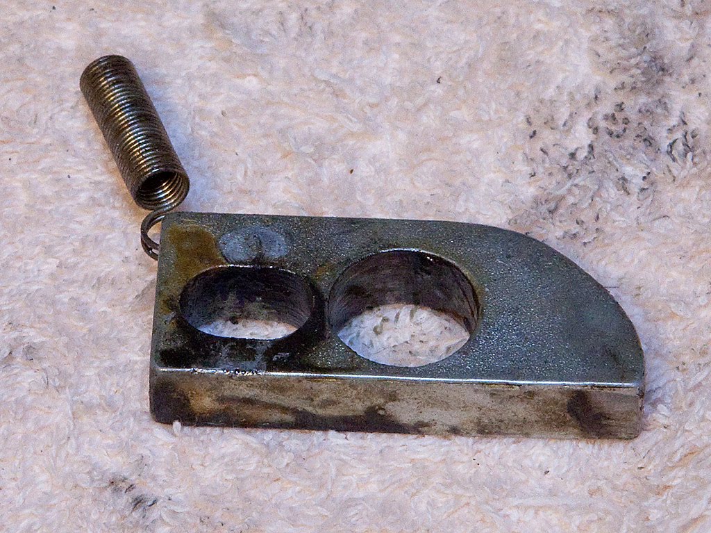
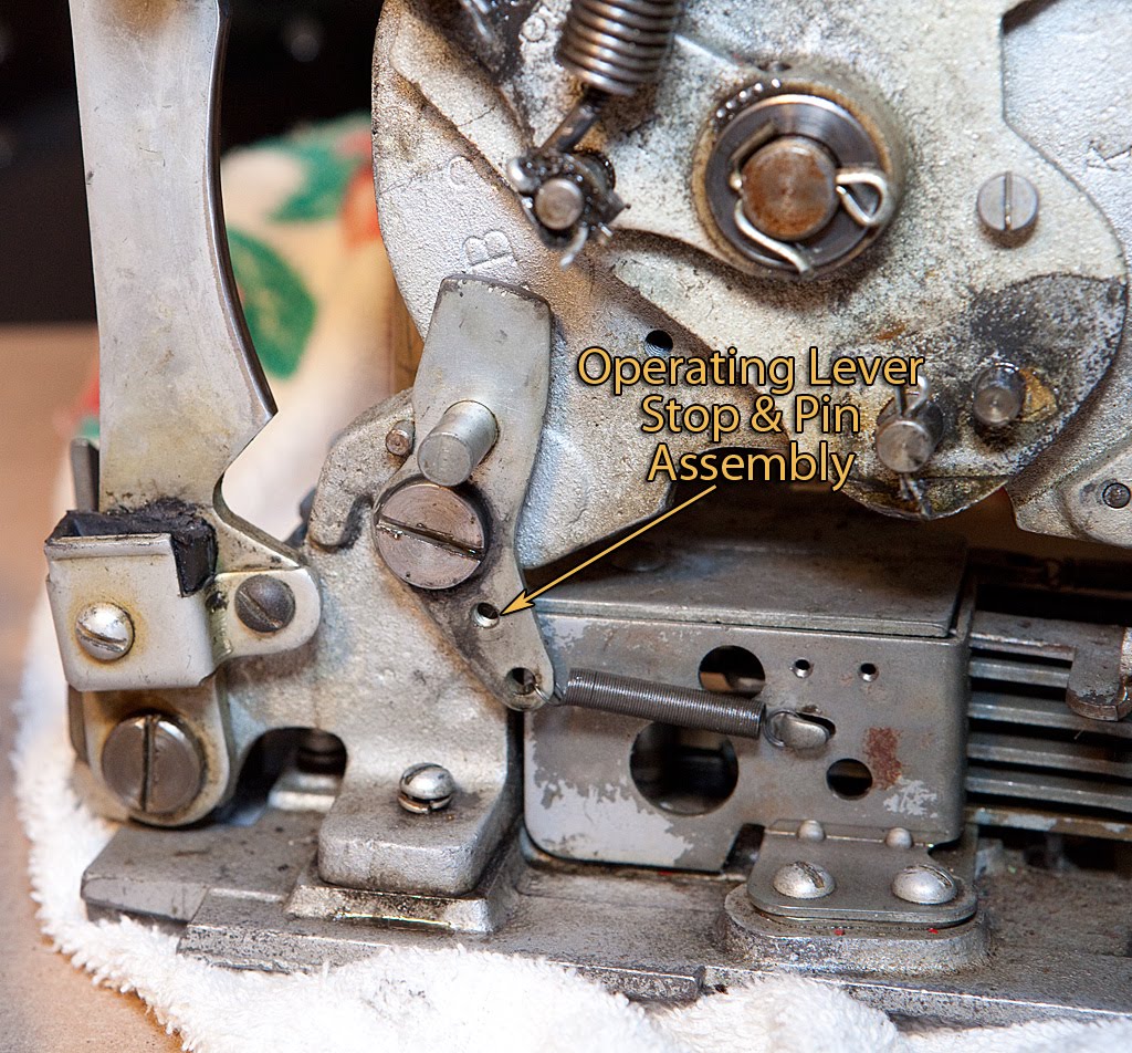
Another easy part to remove is the operating lever stop pin, which is secured by a single shoulder screw and related spring.
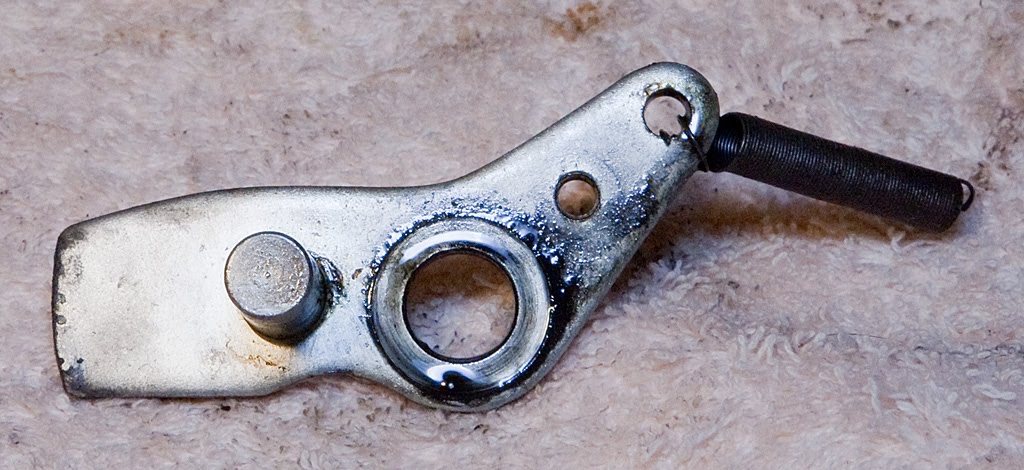
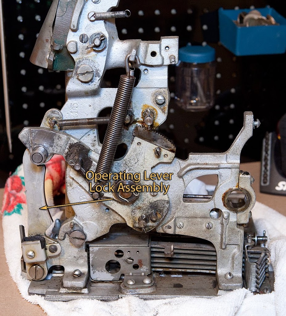
The operating lever lock assembly is ready to come off, and again we need only remove a single shoulder screw and related spring.
Let’s take a closer look at the rubber bumper attached to this piece:
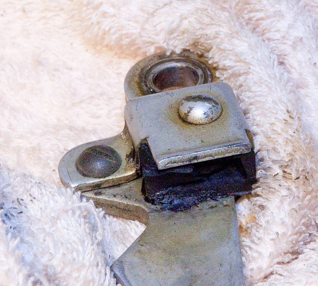
Yuck. This part obviously isn’t doing much good since it has almost totally disintegrated. We’ll have to replace that before reassembling the machine.
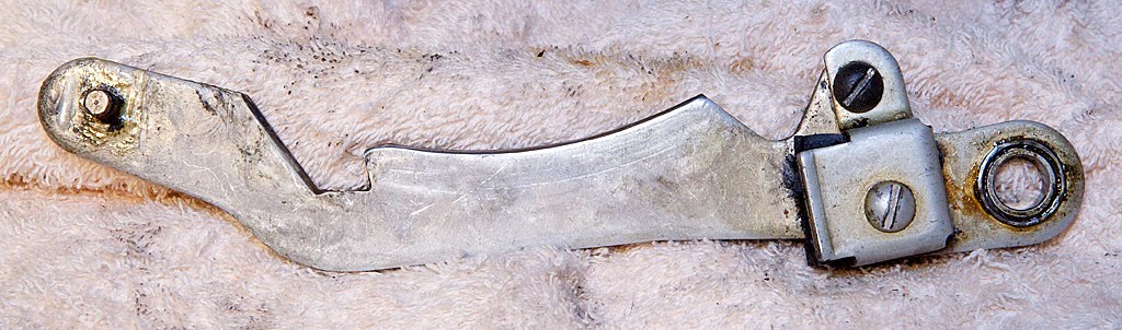
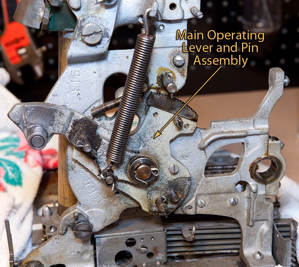
Now we’re ready to remove the main operating lever.
Once again, a single cotter pin and a spring attach it to the frame.
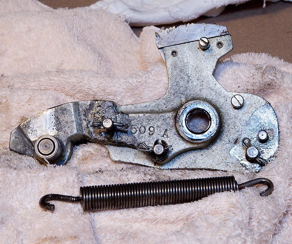
This is a very substantial part that does the job of transferring energy from the handle to the mechanism itself. We’ve also got another small dog to remove, and it’s no more difficult than the last one.

The frame is starting to look pretty bare… take a look.
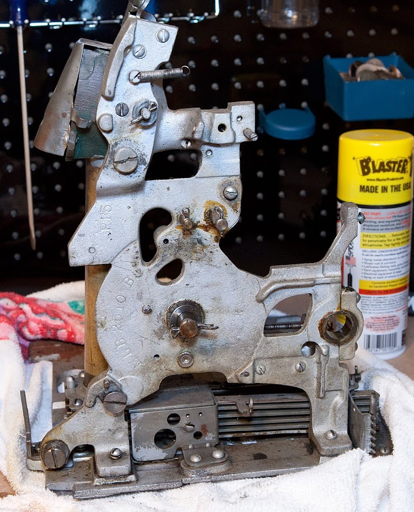
The only parts attached to the frame that need to come off prior to the removal of the frame itself are related to the coin tube, and they are only secured by a couple of screws.
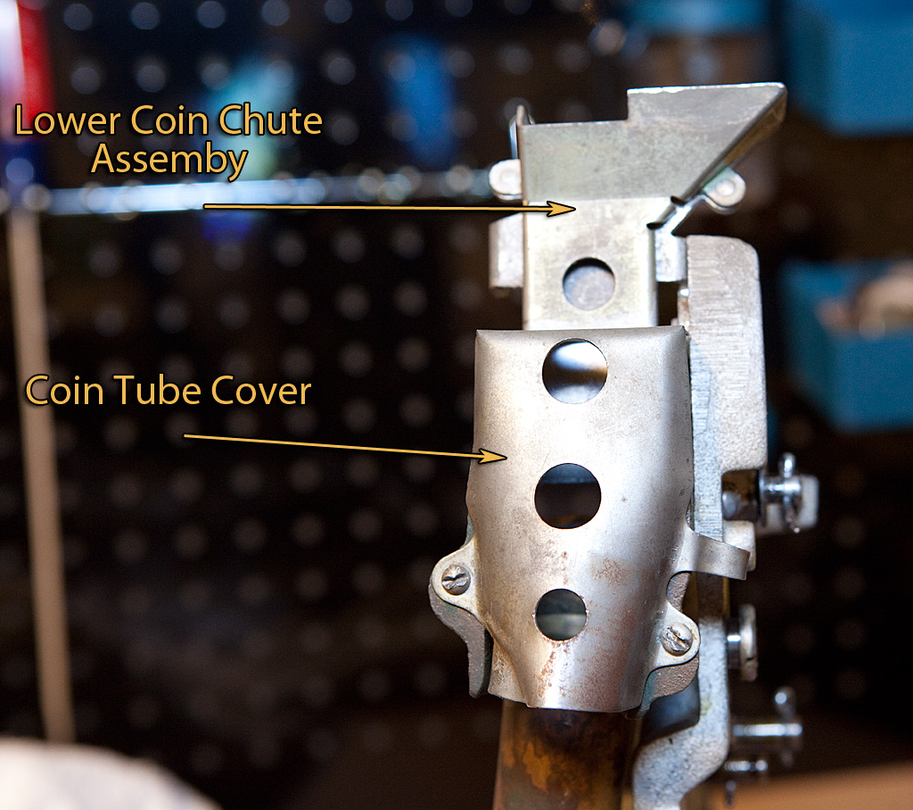
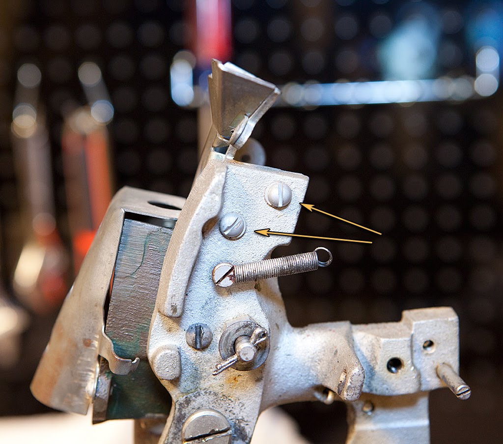
The lower coin chute assembly is secured to the frame by a couple of screws shown above, and the coin tube cover is attached to the coin tube by a couple of screws that should be pretty obvious.

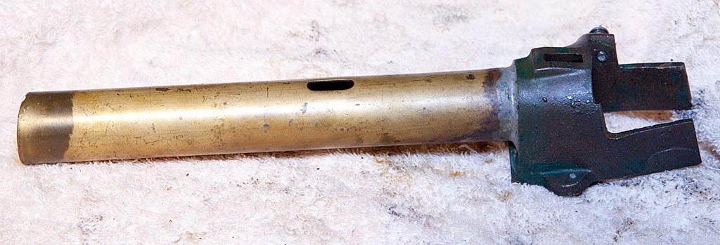
Now, on to the coin tube itself.

The coin tube is where all the coins used for non-jackpot payouts are stored, and is connected to the frame by a single screw pictured below. Once the screw is removed you can lift the tube straight up.
That’s the last of the parts that need to be removed from the frame… now we can remove the frame from the base plate by removing two screws as shown below. These two screws are sometimes difficult to remove, so you may need to apply some WD-40 or a penetrating solvent like B’laster. Just a quick word about B’laster… it’s wonderful stuff. It may not free up every frozen, rusted screw, but it does a heck of a job. It’s great stuff to have around.
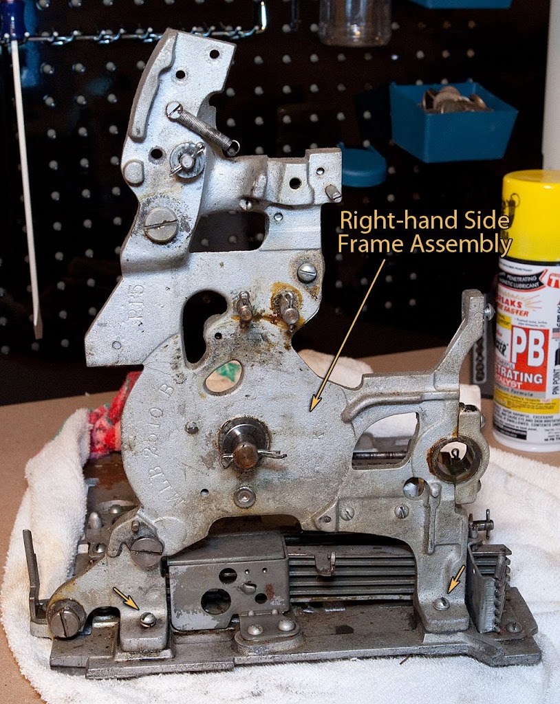
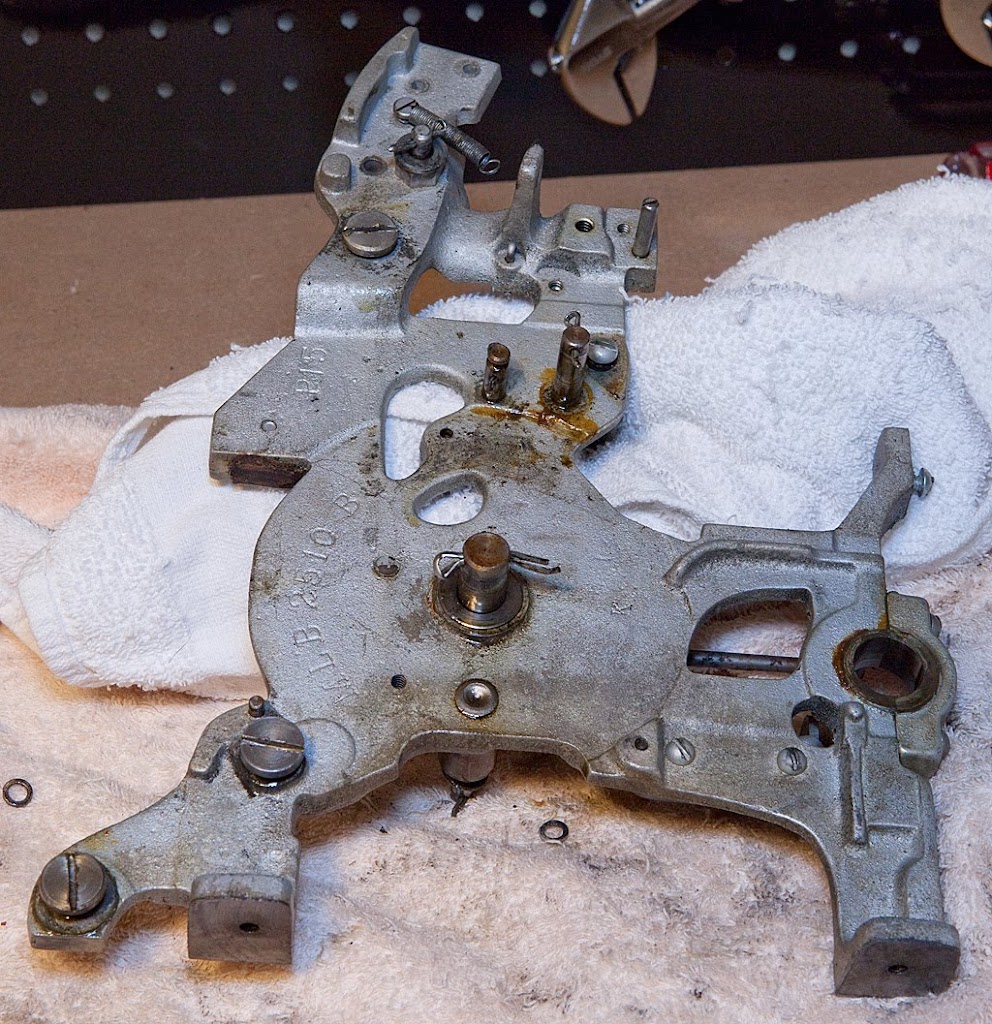
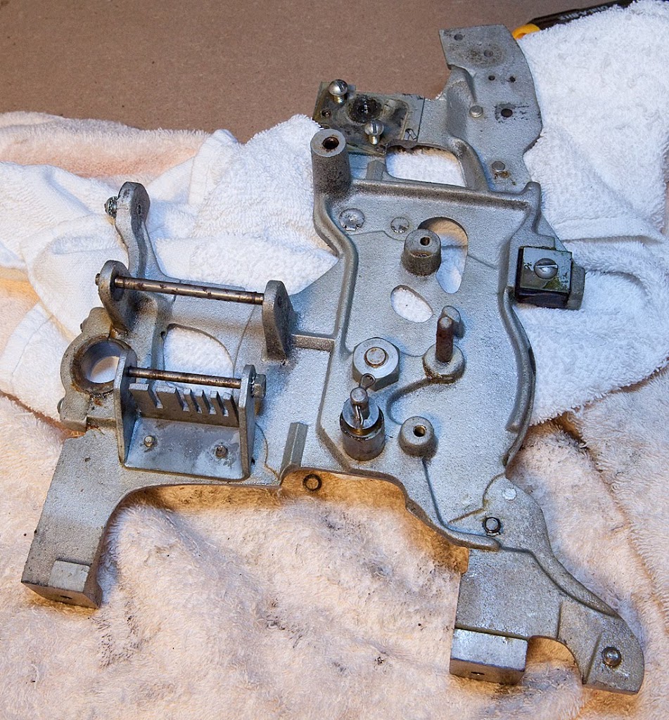
In the photo above you can see the two shafts we removed and replaced earlier, along with another bumper that probably needs to be replaced. Let’s take a look at what’s left of the mechanism.
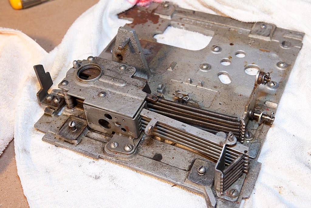
All of the parts left on the base plate are related to the horizontal payout levers or the coin slides. We’re in the home stretch now, and we’ll tackle those parts next.