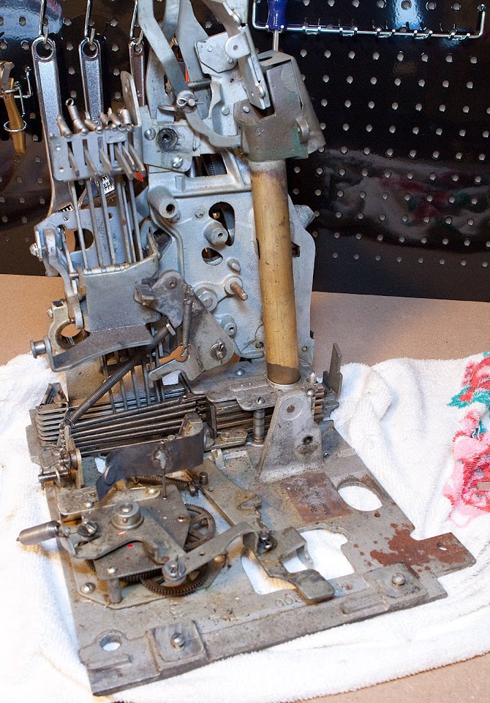
The next part of our antique slot machine restoration is the removal of the timing lever, pictured below.
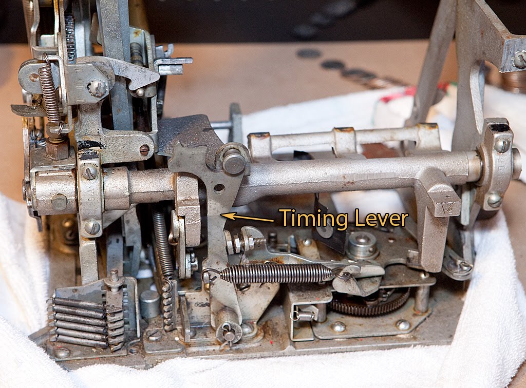
The timing lever’s job is to trigger the vertical payout fingers so that they travel forward and detect any winning combinations on the reels at the end of the mech’s cycle. It’s held in place by a cotter pin and a spring that is attached to a lever on the clock assembly. Removal is pretty much self-evident.
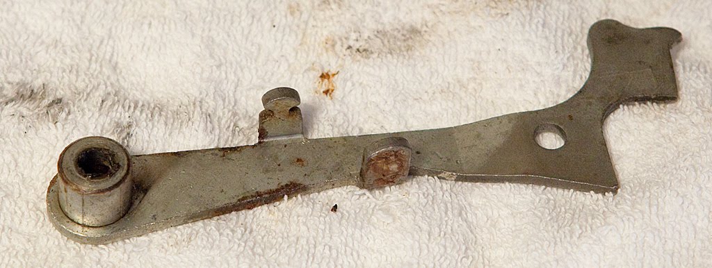
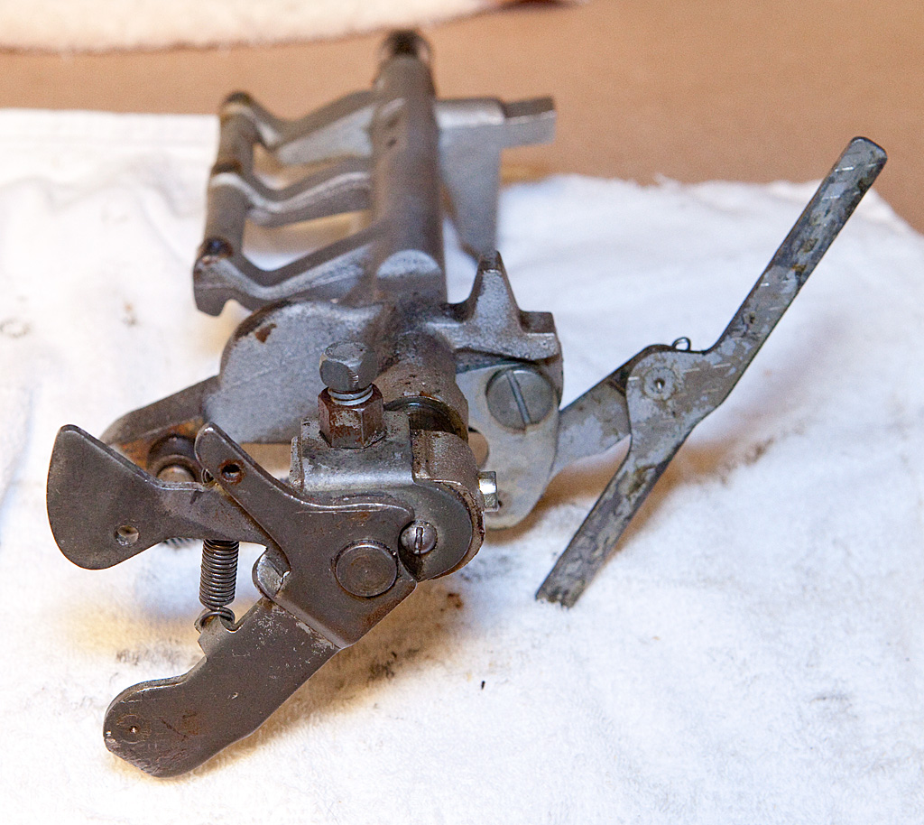
Next up (or more appropriately off) is the timing lever link assembly. Take a look:
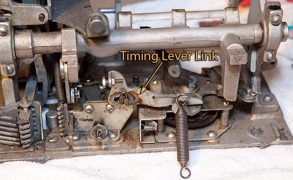
The timing lever link assembly provides an interface between the timing lever (that we just removed) and the clock assembly. On later Mills machines (like this one) there is an adjustment screw that allows you to vary the timing of the payout fingers’ release. Optimally, the fingers will release halfway between the stop of the third reel and the point at which the payout slides are released. Anyway, to remove the timing lever link assembly, remove the cotter pin under the adjustment screw on the left of the part, then swing the part out to get to the other cotter pin pictured below.
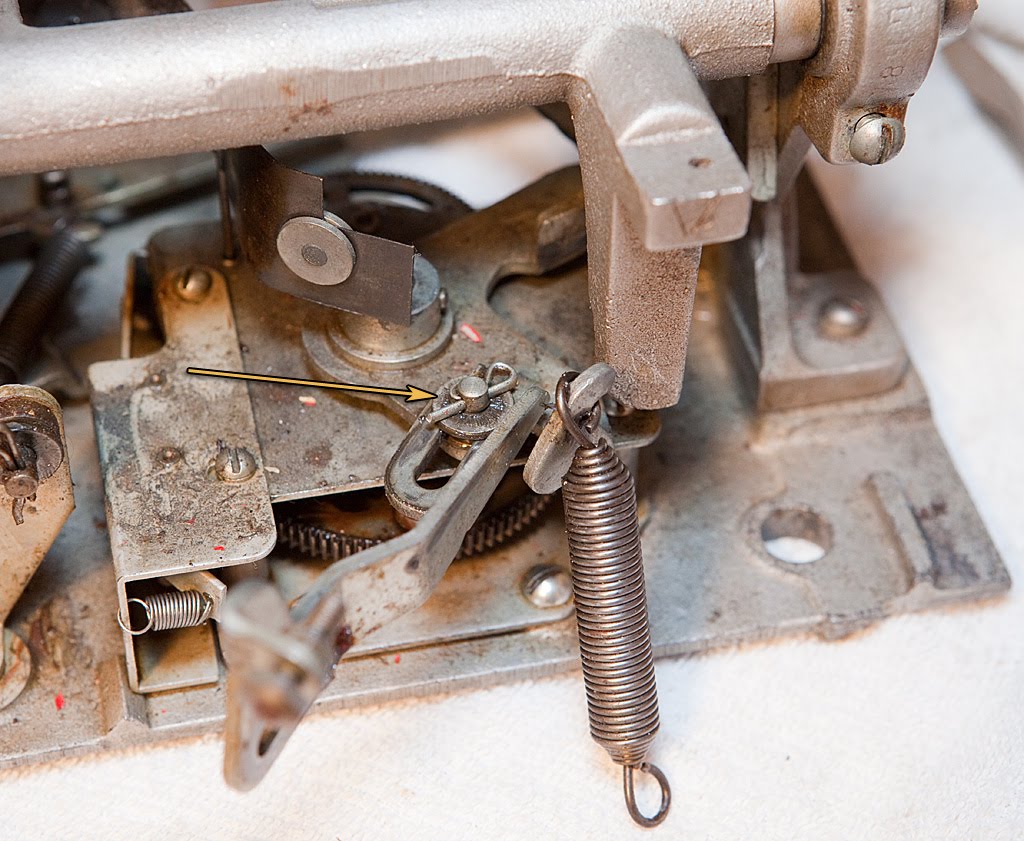

I’d recommend leaving the adjustment screw in place for now, particularly if your machine was in generally working condition when you started disassembly.
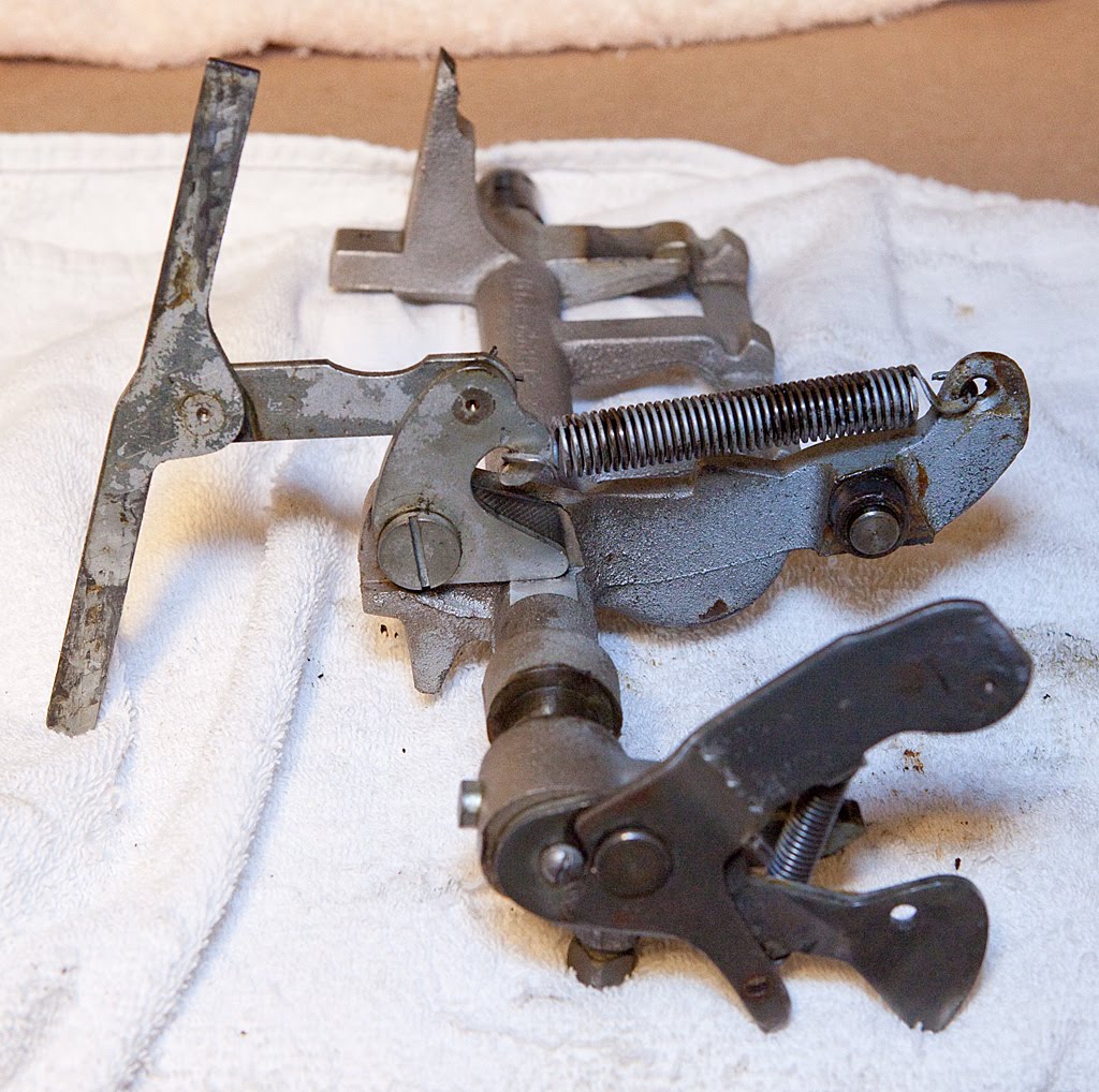
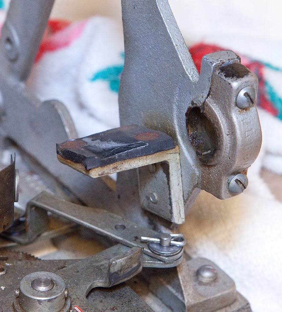
There’s one last part we’re going to remove before taking out the main operating fork, and it’s a little hard to see. It’s a small bracket on the back of the timing lever bracket and stud assembly. It is secured with two screws, as seen in the photo below.
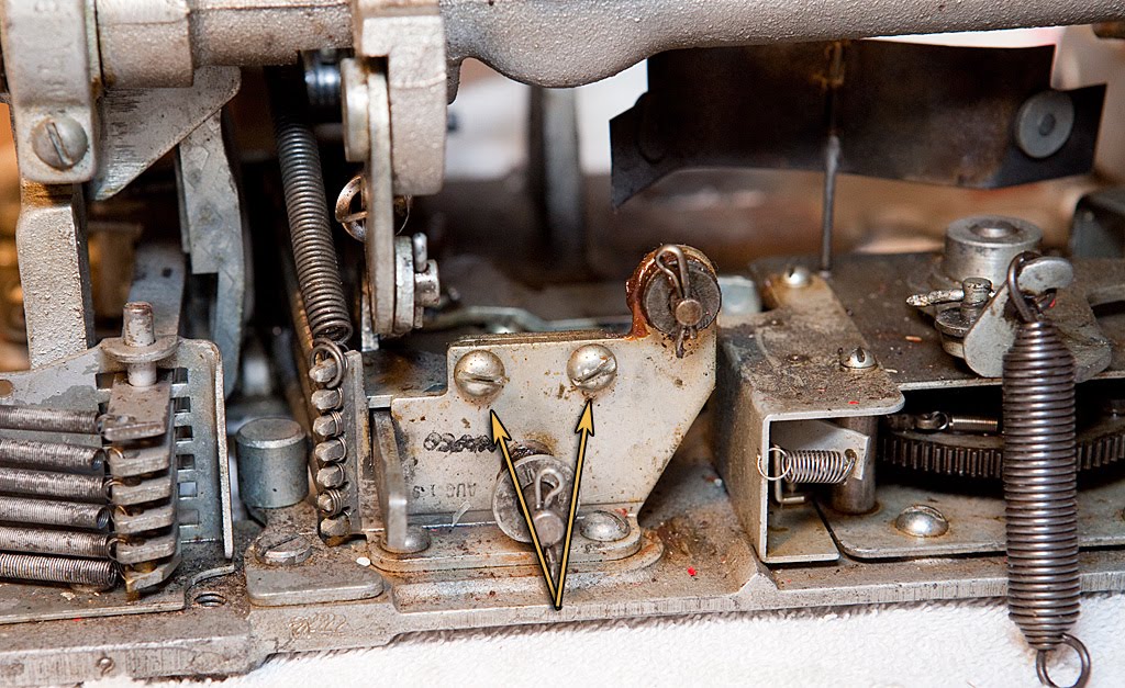
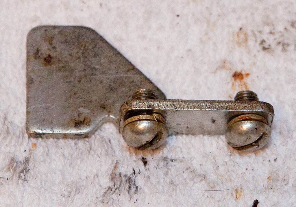
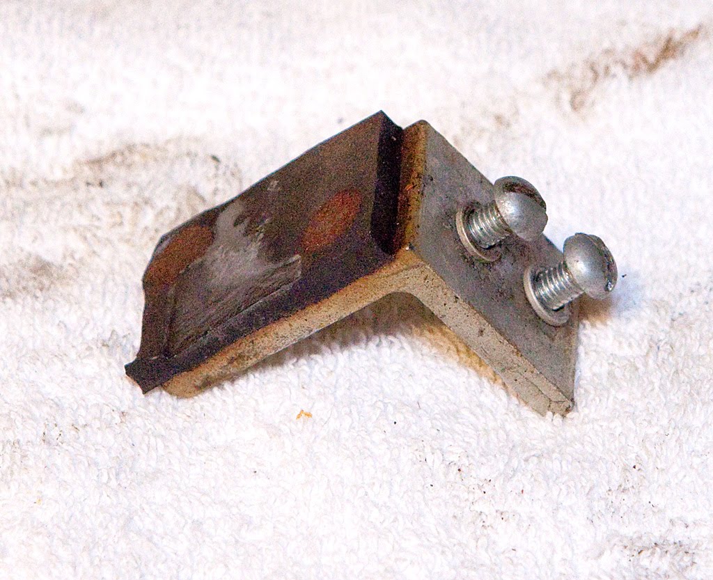
Remove those two screws and the bracket will drop and you’ll have to fish it out of the mech. It looks like this once removed (with the screws replaced, of course):
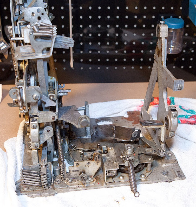
With that part out of the way, we are free to remove the main operating fork, which is somewhat like the spine of the slot machine. When the machine is cycled, virtually every part of the operating mechanism depends upon the main operating fork. Removal of the fork should be pretty easy now that we’ve removed so many parts. The fork is secured by four screws as shown in the two photos below.

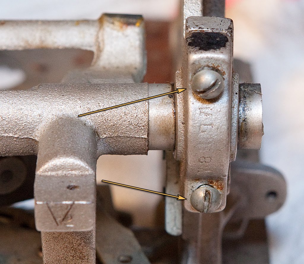
Each pair of these screws secures a removable portion of the main operating fork bearings. It’s important to note that these bearings should be replaced exactly as they were removed, meaning that you should keep the right one on the right and the left one on the left. You should also keep them aligned the same top-to-bottom, so be sure to keep them straight and replace them immediately after you remove the main operating fork assembly. Here’s what the fork assembly looks like after removal:
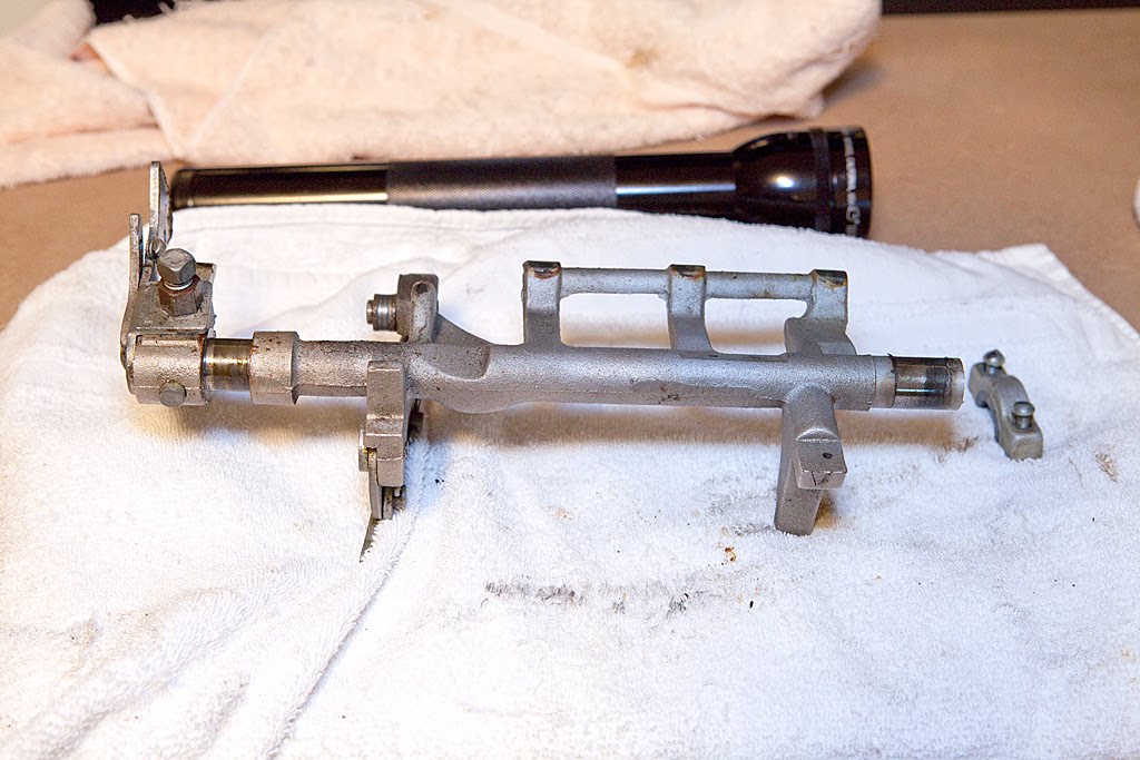
As before when we removed the rear bracket, we’re not going to attempt further disassembly of the main operating fork assembly at this time. We’ll tackle that later during cleaning. By the way, notice the grey paint on the spring above. That’s a sure sign of someone taking bad shortcuts.
The mechanism certainly looks different now… let’s take a look.
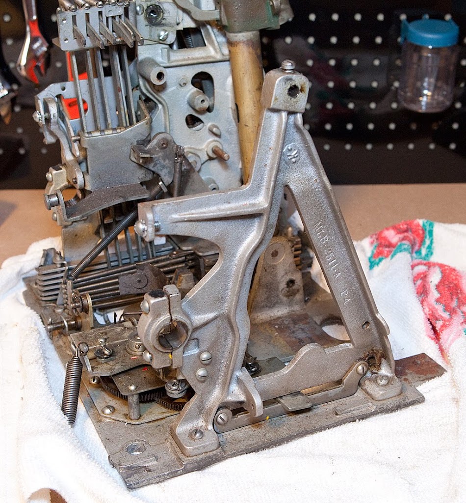
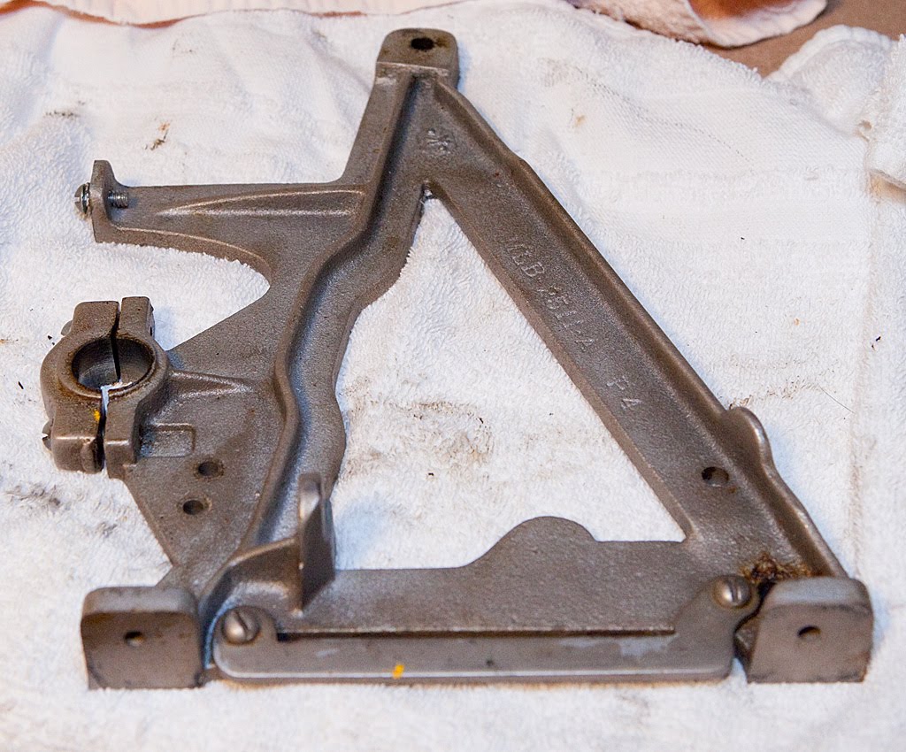
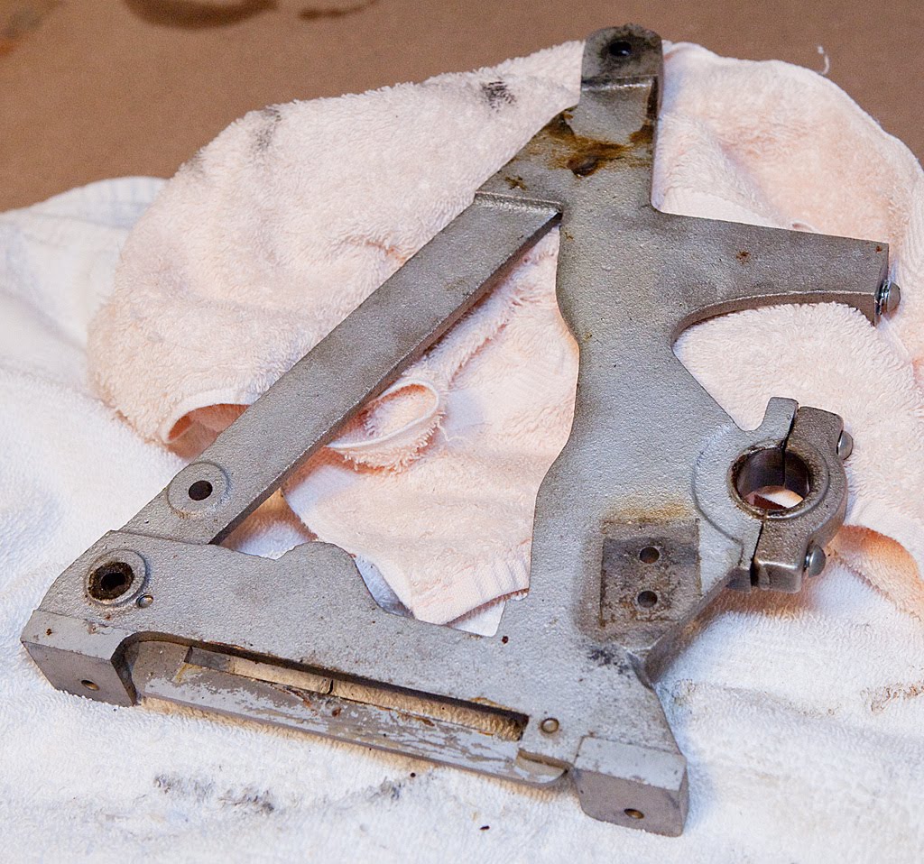
The A-frame pictured above should come off easily now just by unscrewing the two screws that attach it to the base plate, but there’s a small part that I’m going to remove first.
This part is called the felt pad bracket and assembly, but it sure doesn’t look like there’s any felt on this one. Removing it is a snap, just undo the two screws securing it to the A-frame, then remove the A-frame itself from the base plate.
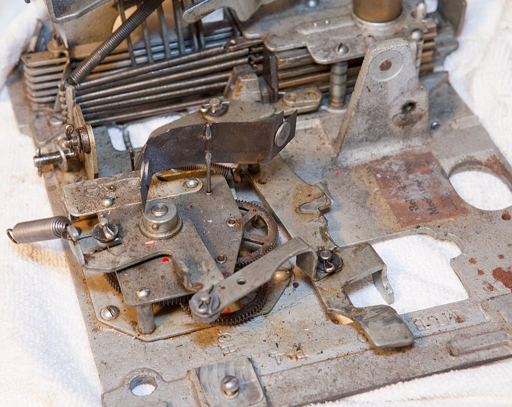
Before we move on, let’s take another look at what’s left of the mechanism.
It definitely looks different. Here’s a closeup of the clock mechanism:
If you’ve never taken a machine completely apart before, take some time now and play with the different parts you see. Take note of how they operate and it will greatly enhance your understanding of how a mechanical slot machine operates.
I’m not sure if I mixed up the main operating fork bearings. What will happen if they’re not replaced with their former mate? Thanks, Barry
Hi, Barry. Mixing up the bearings isn’t the end of the world. The worst thing that can happen is that the mechanism may not move as smoothly as it could, or that the bearings might take a bit more wear and tear. Very often, however, you can figure out which bearings go where by looking at them very carefully. You may see a slight groove inside that you can match up with its mate.
If you think that the bearings have been reversed or switched around, you might think about putting them in place around the fork a few different ways and see which combination seems to operate the smoothest.
Make sense?
Also, sometimes you will find that a previous slot-jockey has marked the bearings with paint. In the photos above you can see some black paint on the top of each bearing piece, and usually that spot will denote the top of the part.
Thanks for the quick reply. I’m about to make an “anchor” out of this slot machine!!! I’ve pretty much cleaned and lubed everything and hoped that would solve my problem. I didn’t really remove much except the reel bundle, the clock and whatever else connected directly to the clock. Here’s what’s happening: 1. The vertical levers do not pull back far enough to clear the discs and once the release cycle kicks in, the discs remain stationary. 2. the kicker doesn’t fully engage the notches……hence the reels do not turn. About all that is happening is that it goes through the wind up cycle, releases during the the release cycle without doing much of anything in the ensuing unwind cycle…..except for the clock turning. Any clue? Thanks, Barry
Also….forgot to add that the stop levers do release and then engage during unwind cycle. However, the left lever (when faced from front of machine) only releases for a nanosecond. Barry
Barry, it definitely sounds like you have some issues. Was the machine working before you started dismantling it?
It’s hard (at least for me) to guess at a cause without seeing the machine, but here are a few things to check. First, make sure that the anti-check payout hook (if present) hasn’t gotten out of position. I’ve seen these cause problems before, particularly if the part is worn or broken and someone reassembles the machine improperly. Next, check the vertical payout pushback lever assembly and make sure that the timing lever is engaging it properly. If I had to guess, I’d say this is where your problem lies. Let me know if that doesn’t make sense and we’ll try to figure it out together as best we can.
The machine didn’t really work when I got it from my now deceased step father. Jack was one of these guys who thought he could do it all! But most of the time, someone else had to fix what he thrashed. What I’m seeing is what you mentioned above….that is, the timing lever is not engaging the vertical payout pushback lever properly. It doesn’t seem to get the elevation it needs to engage the pushback lever……I can do it manually and the pushback lever will snap into place thereby clearing the levers from the discs. But even though I set the levers manually, I can see that the kicker rests on the discs keeping them from turning freely.
You may well have a sluggish kicker, which is a very common problem. Sometimes they are too worn out to work and need to be replaced, but often a bath in some solvent and a re-lubrication will get them going again.
It’s sounding more and more like this machine has some significant issues. Although I’m going to be doing a complete reassembly over time, it’s going to take me a few months to get around to it all due to more pressing concerns. If you are in a hurry, you might want to get the DVD set from ibuyoldslots.com. The production values aren’t Hollywood quality, but overall it’s an invaluable resource.
Do you have the capacity to take some digital photos and/or video? If so, I’d be happy to take a look and see if I see anything obvious.
Yes, I can send you some photos and video clips….but how do I attach them to this website? Barry
Hello Slotter,
Please send me your email address so that I can send you a few pix and videos of my slot machine. My email address is: rowdymoose@yahoo.com
Thanks, Barry