The next part we’re going to remove is a small linkage lever that runs between the clock and the reel stop timing lever.
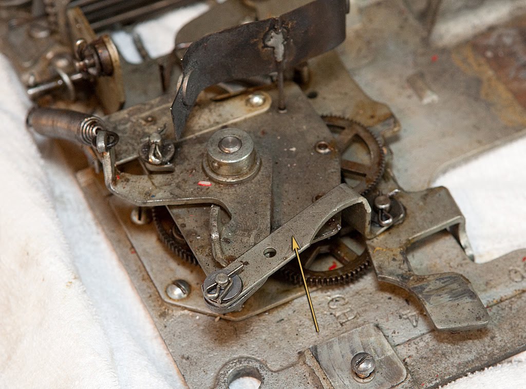
The lever is held on with two cotter pins, so no big deal to get it off the mech.

Next we’re going after the reel timing lever itself.

The reel timing lever is the part responsible for slowly allowing each reel stop lever to come in contact with its related star wheel, stopping the reels in a 1-2-3 order as the clock unwinds. It’s secured by a cotter pin and an attached extension screw.
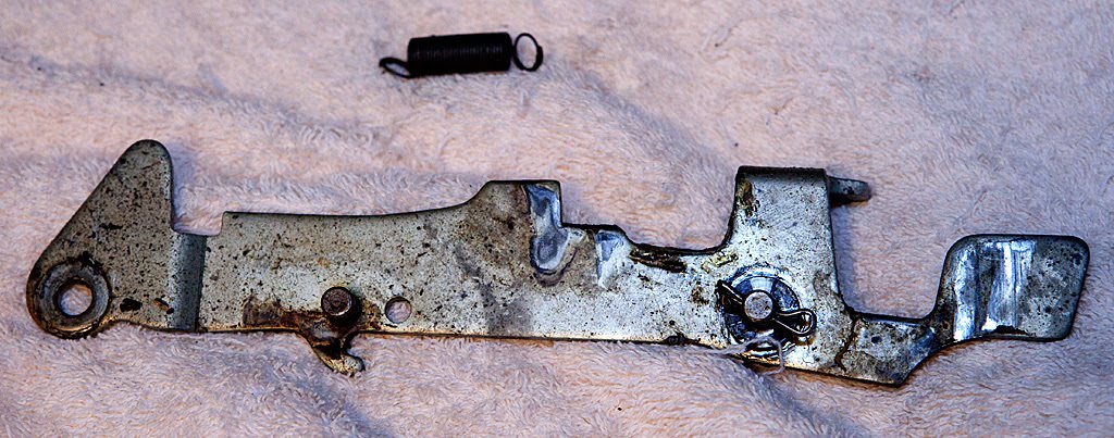
The extension spring must also be removed at this time because it attaches to two ears and isn’t locked into a hole, so if we don’t remove it now we might lose it. More such springs are on the way, so we need to be sure that we have a box or jar in which to store all the stray springs.
Now, we move on to the clock assembly itself.
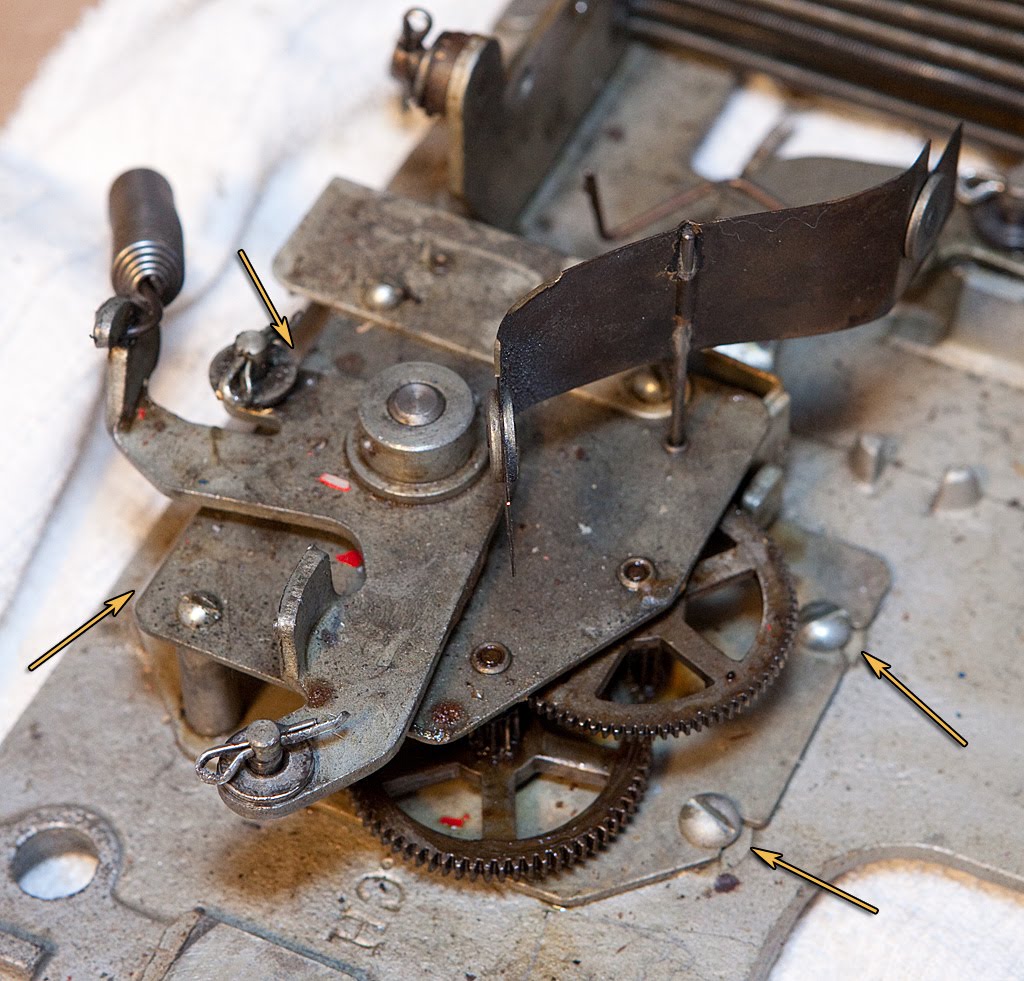
Earlier we referred to the main operating fork as the “spine” of the slot machine mechanism. If the operating fork is the spine, the clock assembly is the heart. If the clock stops, the machine stops.
Removal of the clock is accomplished by removing four screws that secure it to the base plate. Please note that these screws are located directly on the base plate. You don’t want to unscrew the wrong screws here and have the clock come apart. On this particular mech, the front two screws (right in the above photo) don’t even need to be removed since they are in slots rather than holes. Loosening these two screws and removing the two in the back of the mech should allow the clock to slide free.

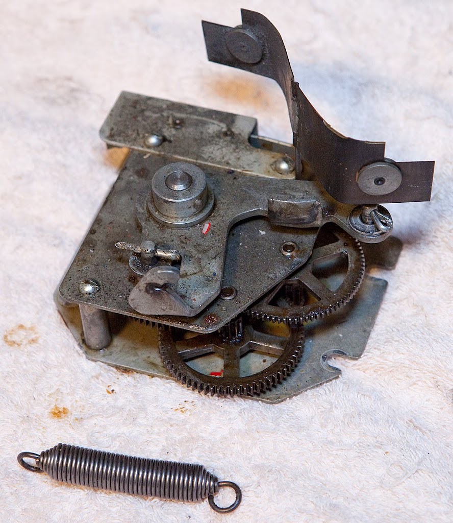
The clock mechanism is pretty dirty, and we may well have to disassemble it and clean each part individually, but I’m hoping that a dip in some solvent and a re-oiling may be sufficient. Time will tell, I suppose.
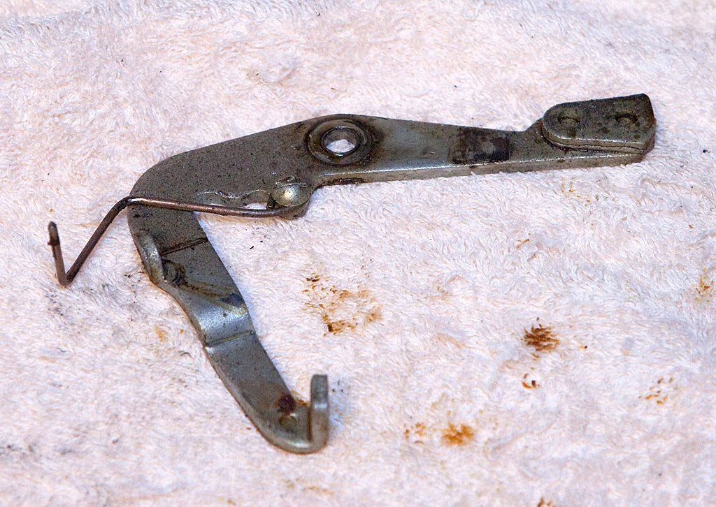
Next, we’re going to remove the payout slide lock lever. It’s secured with a single cotter pin.
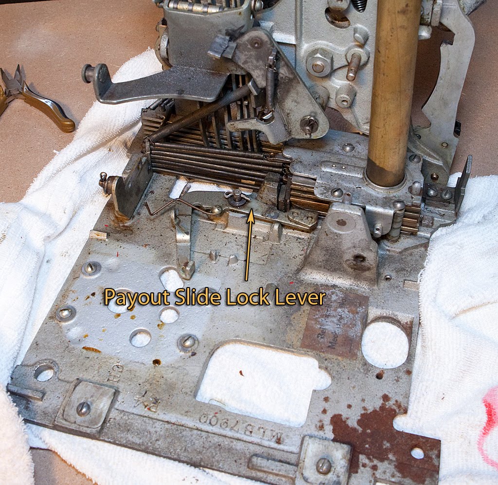
This lever holds the payout slides in place until all the reels have been stopped, the payout fingers have been released and the horizontal payout levers have been tripped (if applicable). This lever being activated essentially marks the end (or at least the beginning of the end) of the mech’s cycle.
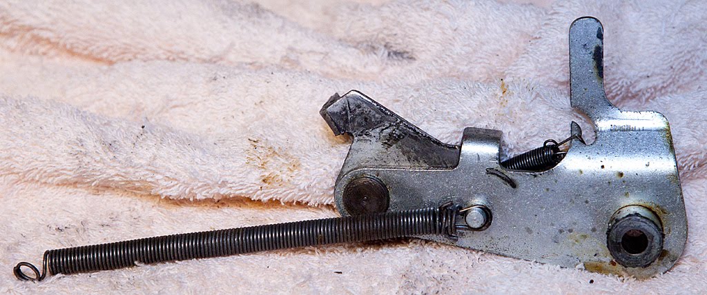
Now it’s time to remove the kicker assembly. It may have been hard to locate in earlier photos, but you shouldn’t have any trouble now.
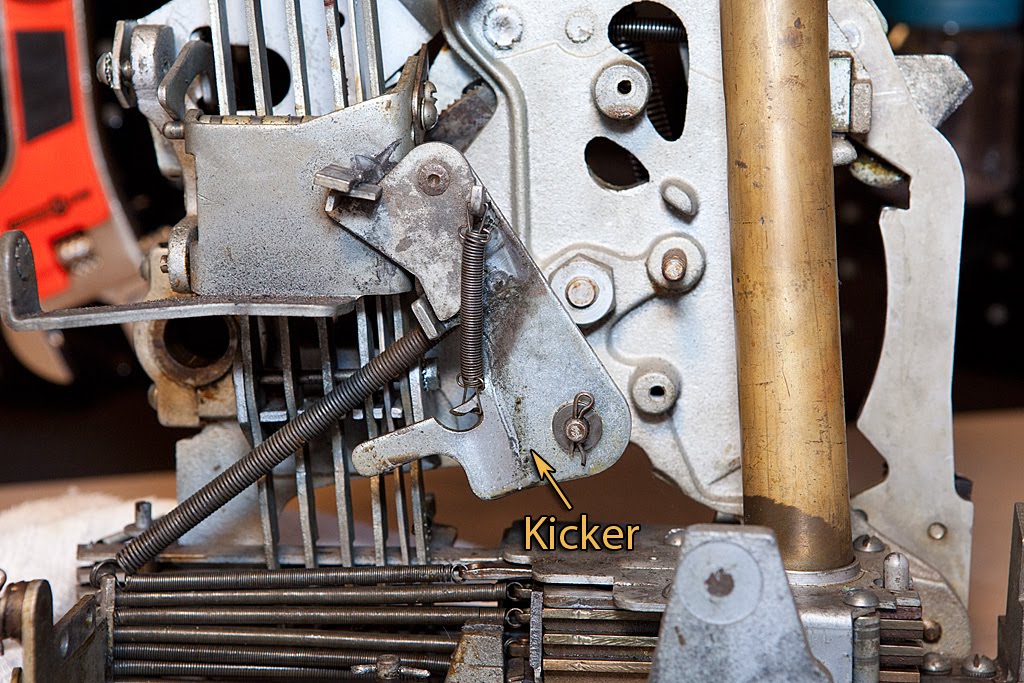
The kicker is attached by a single cotter pin and a long extension spring, so it’s easy to remove. Before we do that, take a look at the photo above. That long extension spring provides the direct power that spins the reels by pulling the kicker as it presses against the underside of the payout discs, kicking them into rotation. The second spring that is integral to the assembly pulls the top portion of the assembly out of the way after it kicks the reels, allowing them to spin without running into the kicker itself.
As you will recall, one of the initial problems I had with this machine was that the reels weren’t spinning. The problem that caused that condition was that the top part of the kicker was gummed up with a bunch of hardened grease, oil and dirt. Since the top part didn’t want to rotate, after the reel discs started spinning they were running into the kicker, which was stopping them again and causing the machine to make a “Clang!” sound as the reel disks were struck like a gong. It’s a common problem, and nothing that a good thorough cleaning won’t fix.
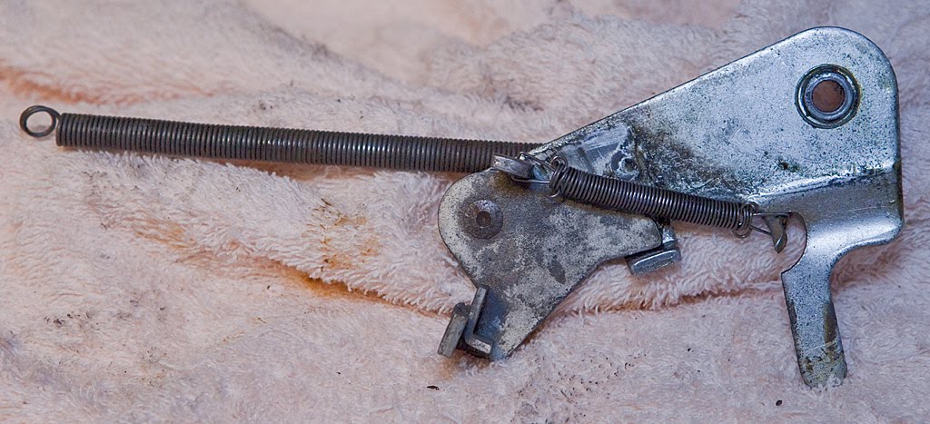
Here’s the kicker out of the mech:
Onward and upward… next time we’ll tackle the payout fingers and some of the related parts.