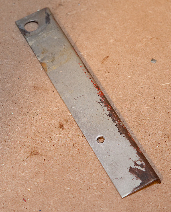
Now we start the task of removing all the various parts from the wood cabinet. Again, there’s no real pre-defined order to this process, we’re just going to remove the parts that are the easiest to access. First, we’re going to remove the levers that lock the back bonnet in place when the case is together.
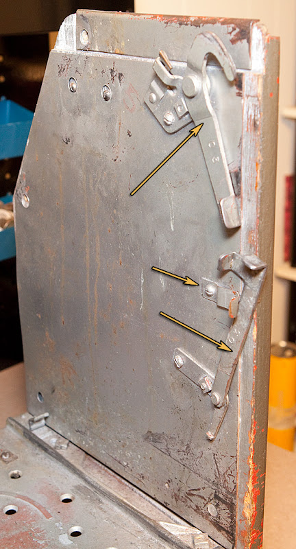
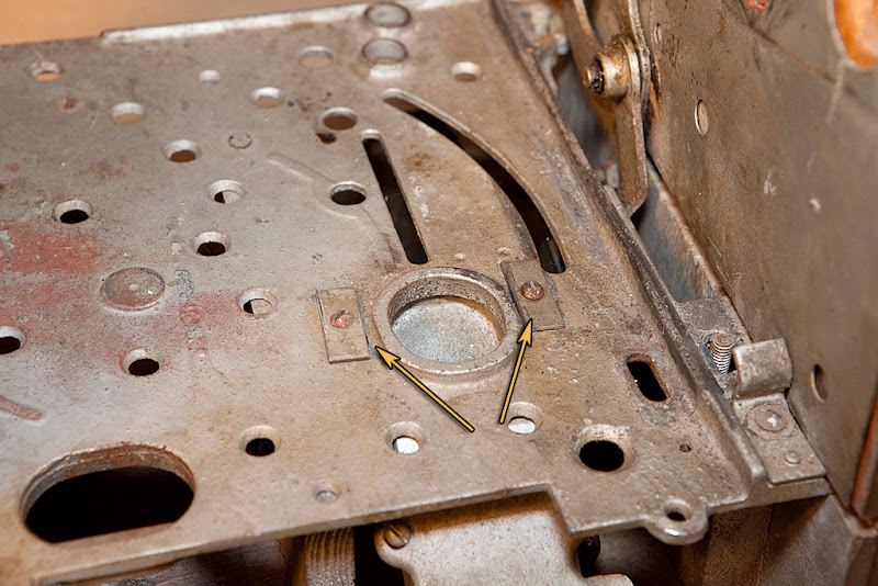
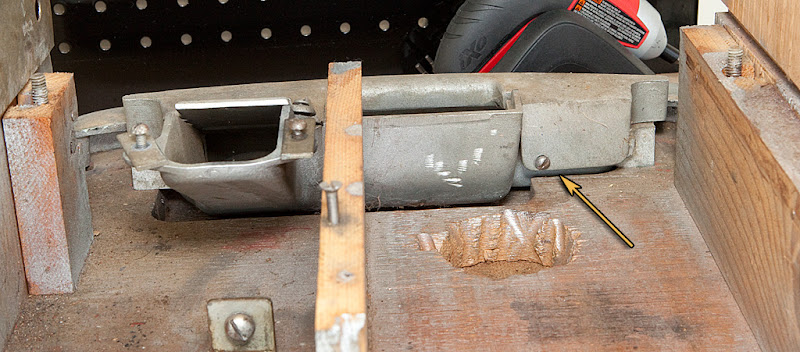
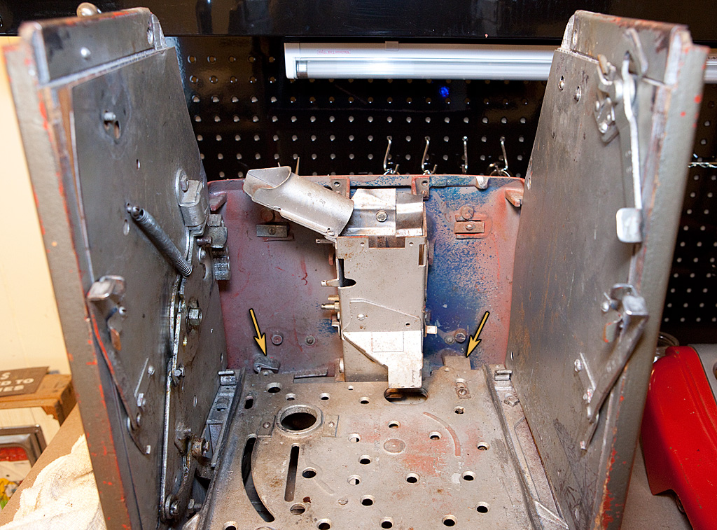
As you can see, this particular part is already missing from the handle-side of the machine (it was in the cash box when I bought the slot, so at least I won’t need to find a replacement.) On the other side, you can see the part in question at the top of the cabinet. It’s secured with a screw and a carriage bolt. While we’re at it, we’re also going to remove the parts indicated by the other arrows. The bottom part is a locking bar that keeps the mechanism base plate in place (held onto the cabinet again by a screw and a carriage bolt) , and the middle part is a very simple holding device that keeps the locking bar out of the way when you are removing the mech from the case. I’m not going to photograph these parts separate from the cabinet since they are all very simple and self-explanatory. I’m removing all of these parts from both sides of the cabinet.
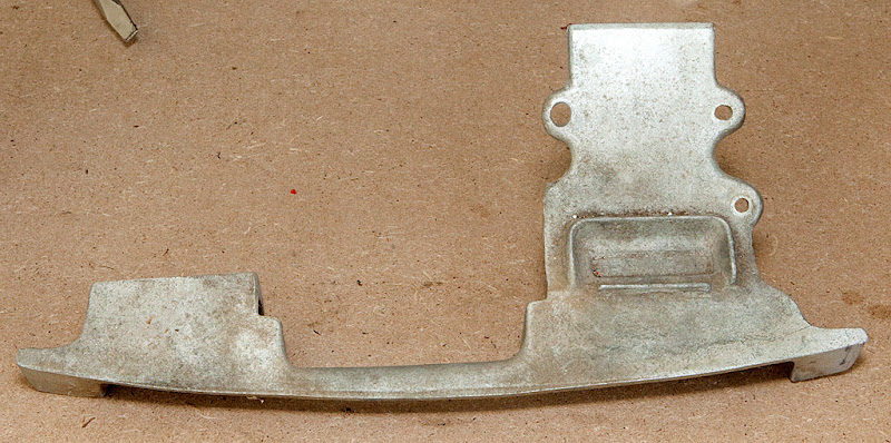
Next, I’m going to remove the armor plating from the non-handle side of the cabinet.
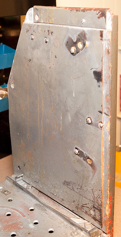
This is a simple part that was designed to inhibit cheating, making it harder for someone to drill a hole in the side of the cabinet and use a wire to stop the clock, trip the jackpot or otherwise manipulate the mechanism. It’s easy to remove, but depending on the screws left in the cabinet you may have to remove a few.
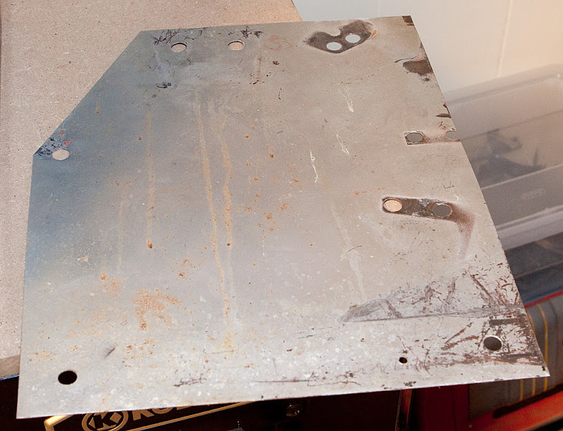
With the armor plating removed, we’re down to bare wood on this side of the cabinet.
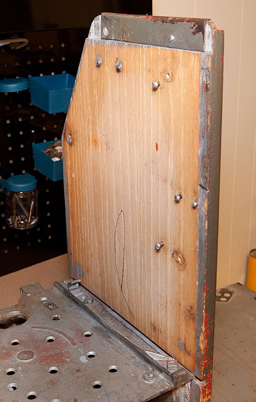
At the very top of the cabinet in the photo above, you can see one last metal part attached to the cabinet side. This is another security feature, and is held in place by one or two screws. I’m going to remove it now, although some people advise leaving it in place to add some structural integrity to the cabinet side for later when we separate the sides from the base. In reality, that’s probably a better approach, so let your best judgment guide you.
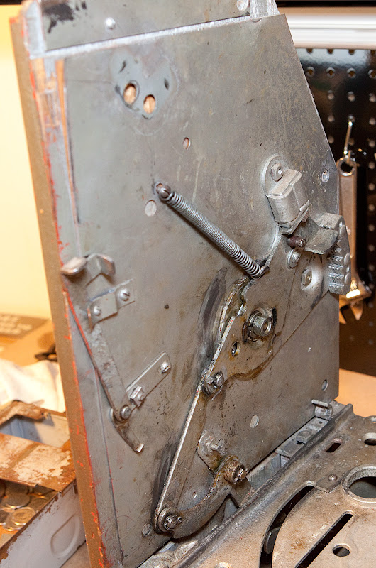
Now we’ll move along to the other side of the cabinet, where we’ll find all of the handle hardware.
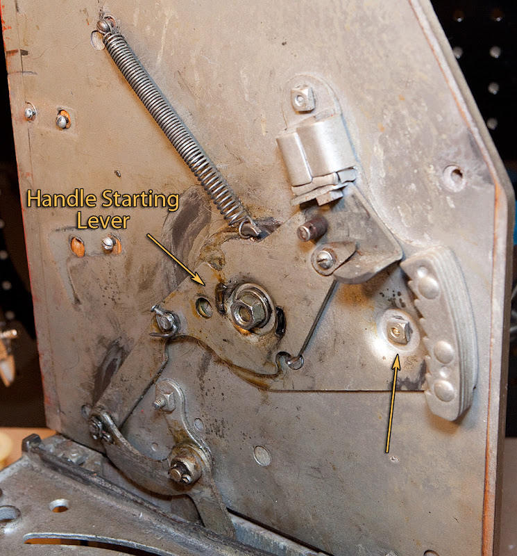
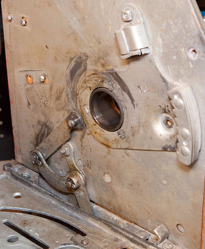
The handle starting lever needs to come off, and it’s secured to the case by a spring and to the pump linkage by a cotter pin (or in this care, a bent nail.) It’s also secured to the handle itself by a large nut in the center. Please also note the arrow above that points to a carriage bolt. This doesn’t need to be removed just yet, but it’s important to note that it is a shorter carriage bolt than many on the machine. The handle starting lever must be able to clear this bolt/nut in order to work, so remember that for later.
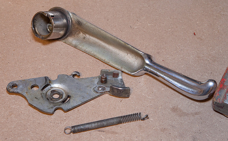
The handle starting lever is missing a small dog and the related spring, but luckily I already have a spare.
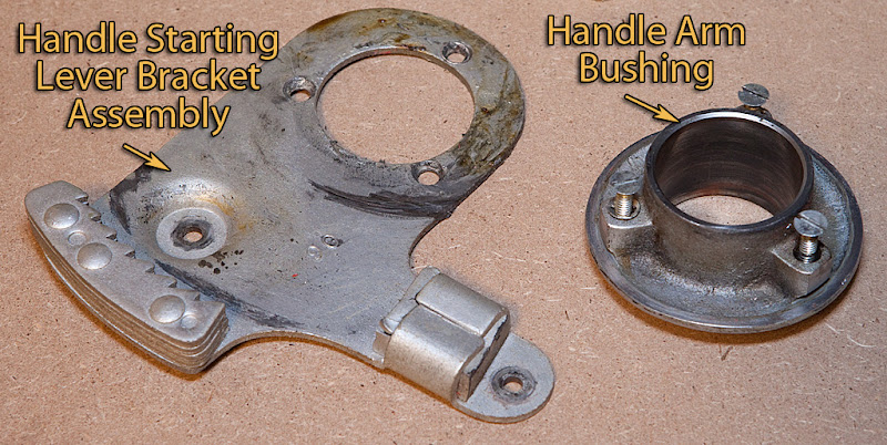
Moving along, let’s remove the handle starting lever bracket assembly and the handle arm bushing.
In the photo above you can see the three screws that connect these two parts together. If you haven’t already removed the short carriage bolt I mentioned above, you need to remove it now. These parts are generally very greasy, so act accordingly.
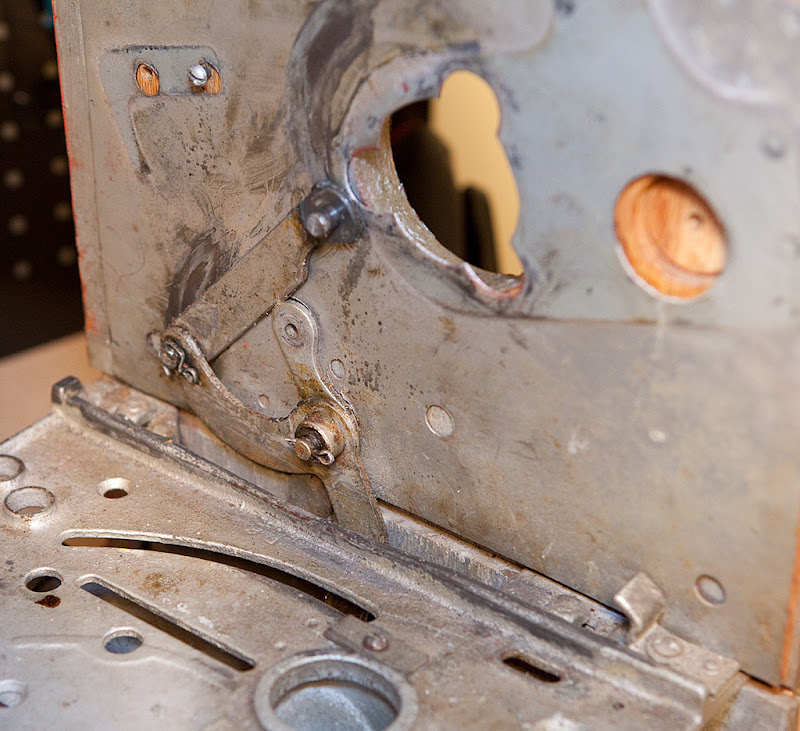
Here’s the cabinet with those parts removed.
Now we’re going to look at the front of the cabinet and talk about a few parts.
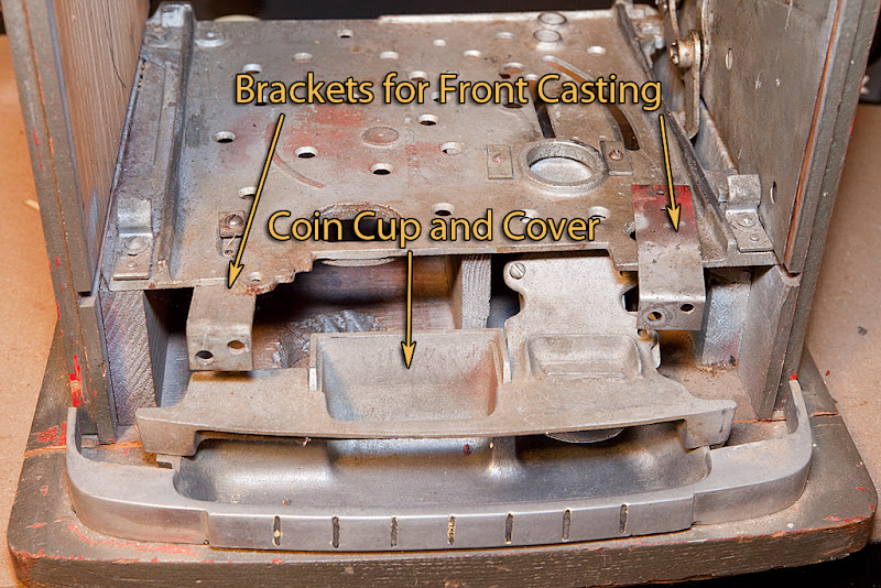
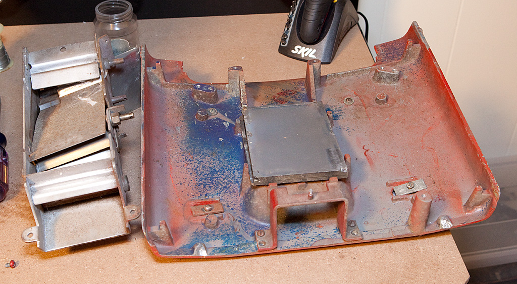
We’re going to be removing the sub-base plate next, which is the large cast iron plate that the mechanism sits on when it is in the case. This part is secured to the bottom of the case by four carriage bolts, two on each side of the cabinet. You should be able to find them easily, but the sub-base is also connected in other places. The two brackets pictured above (one installed, the other just laying in place) are the ones we discussed when removing the lower front casting. They don’t need to be removed in order to get the sub-base out, but I wanted to document them so that you could see where they are supposed to be installed. Also, take a look at the coin cup and cover. They are connected to the sub-base plate by two screws and rectangular washers identified below.
Lastly, the sub-base plate is sometimes connected to other parts of the cabinet by wood screws as pictured below.

Once you get all of these screws, bolts and such out of the way, the sub-base plate should lift right out.
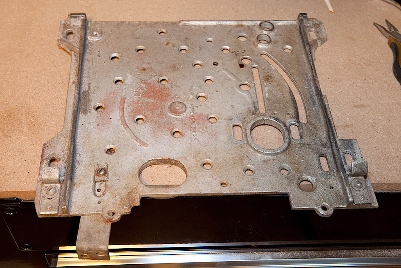
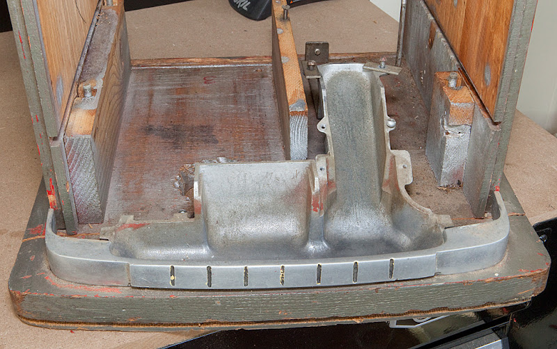
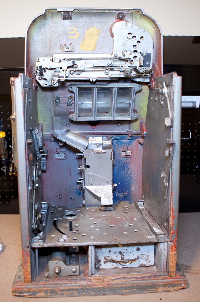
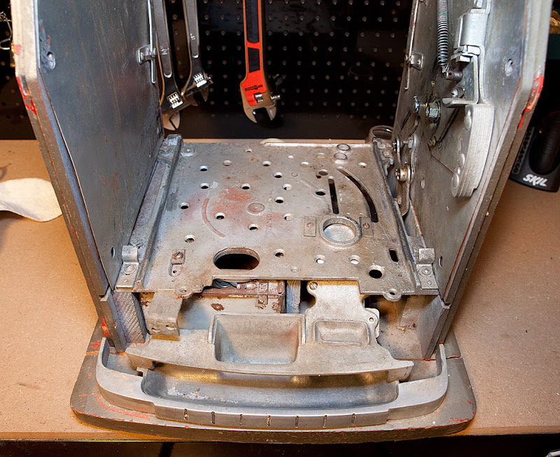
Here’s what the cabinet looks like with the plate removed:
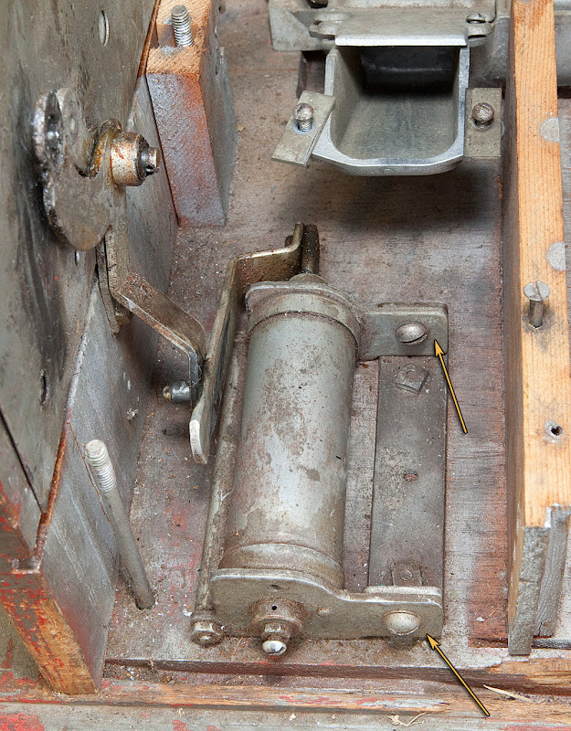
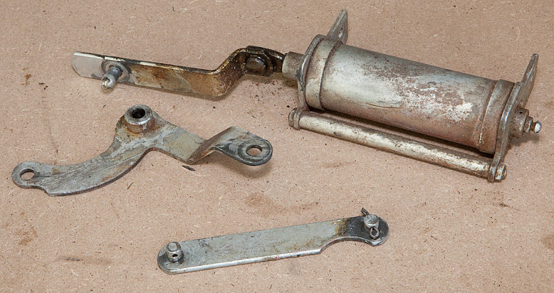
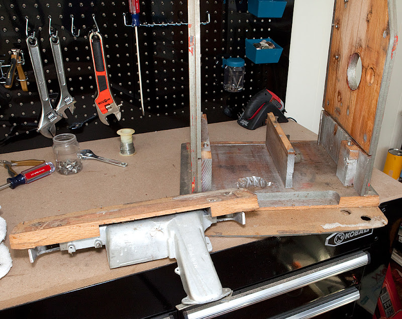
At this point we want to remove the pump and related linkage parts. Here’s what they look like still mounted to the cabinet:
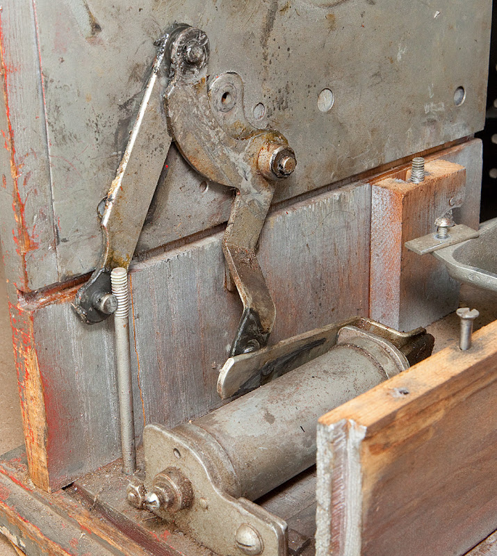
The easiest thing to do here is to remove the pump from it’s mounting bracket, and then disassemble the linkage parts. The pump is held to the bracket by a couple of screws.
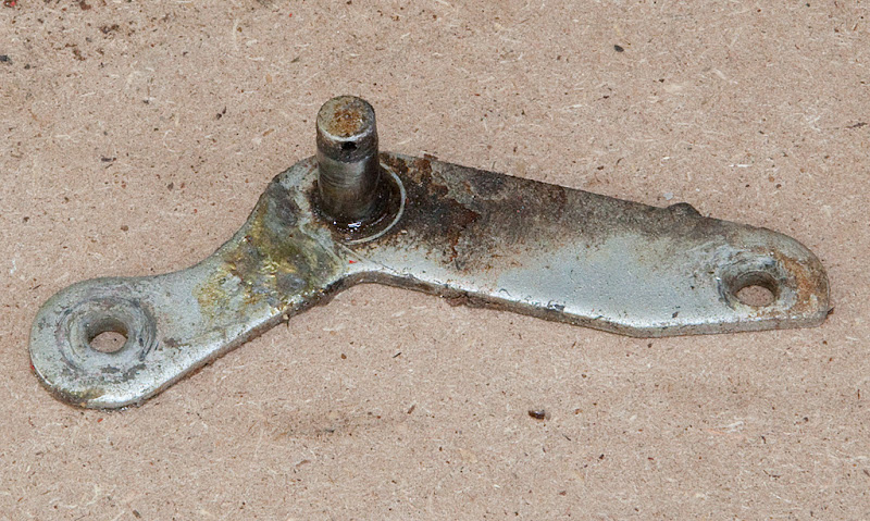
There’s one last piece remaining on the machine, held in place by a carriage bolt.
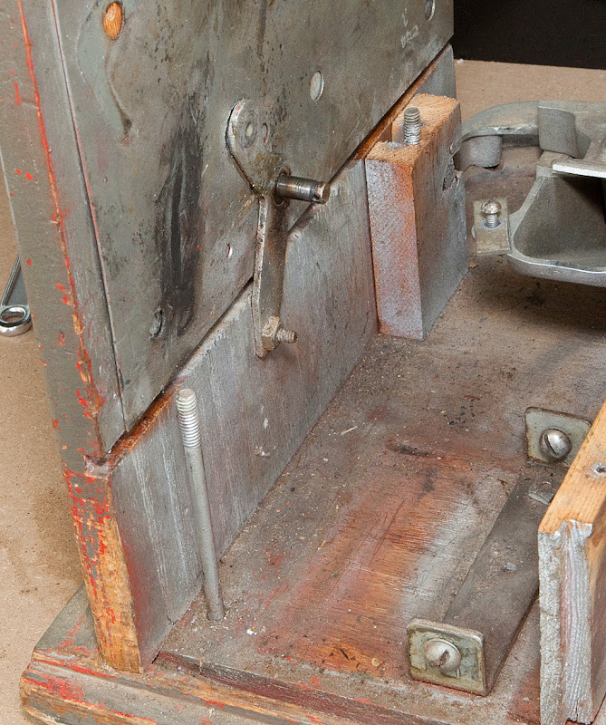
With these parts removed, you can either remove the handle mounting bracket now, or leave it on the cabinet base to provide the cabinet with some added rigidity when we remove the sides. I’m going to leave it in place for now. With this piece removed, the armor plating will be free to come off, and the top rail will also be accessible. I’m not going to photograph those parts since removing them is pretty much the same process that we did for the other side.
Next we’ll tackle the coin cup and cover.
There’s a screw in the back of the coin cup cover that needs to come out, and there may be other screws in more obvious places, but all of these screws should be easy to locate and remove.
That leaves just the coin cup and related molding, pictured below.
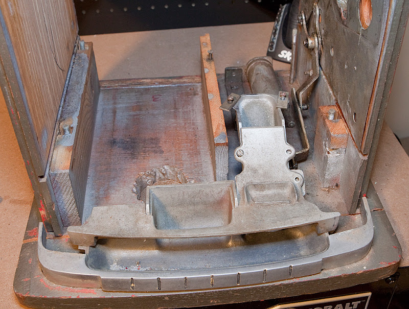
These parts are secured to the cabinet base with a couple of screws, so you’ll have to tip the cabinet up to get to the underside. In this particular case, however, there’s a bit of a surprise waiting for me.
First off, the cabinet base has split and separated at a point right behind the coin cup hardware. I was expecting this, so no big deal there, but it’s also lost some of its thickness at some point and been glued to some sort of fiberboard base. This is not a good thing, since that can’t really be refinished. In addition, someone has cut a very ragged hole in the base itself. You sometimes see this on some vintage machines for a couple of reasons. Some operators would cut this kind of hole to correspond to a hole in whatever stand they were using for the machine and hang a cash bag instead of using a cash box. Other times the operator would cut a hole and use it for hardware that would lock the machine to a stand as a security measure. In either case, this sort of modification is known by the technical term “crap.” Here’s what the remaining portion of the base looks like with the loose piece put in place, and with the fiberboard removed:
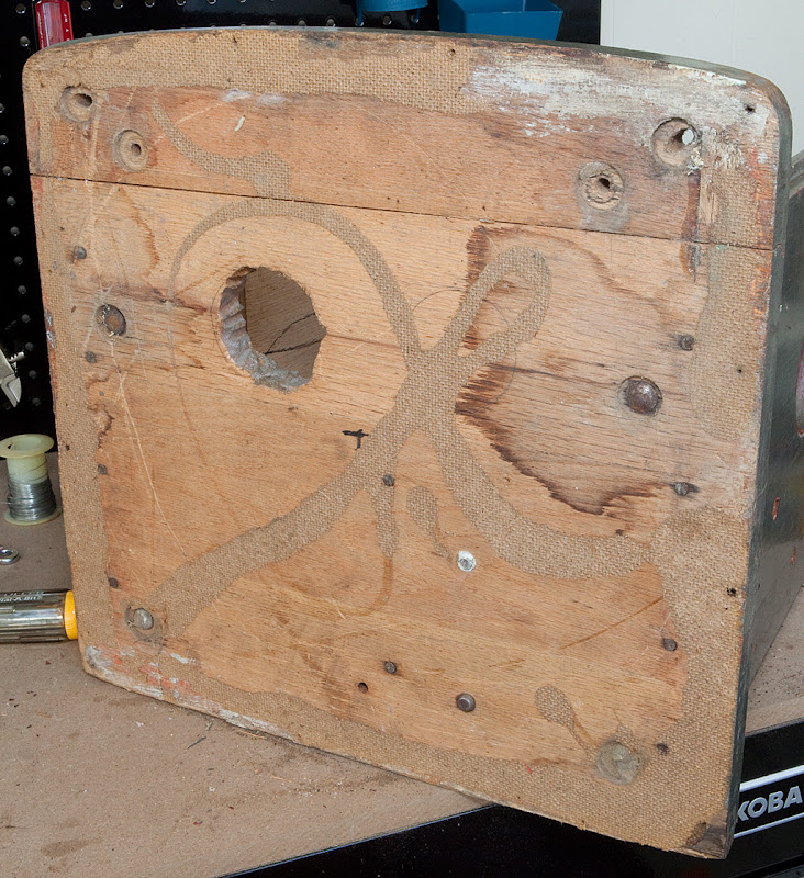
It looks like the base may have sustained some water damage at some point, and that might be the reason for the fiberboard addition.
There are a couple of paths I could take on this restoration, given what we now know about the base. I could glue the cabinet base parts back together and cut a new piece of thin wood to take the place of the fiberboard, but then I’d have to deal with the hole somehow. I could buy a whole new cabinet, or just a cabinet base (both of which are readily available.) I’m not going to decide just yet, however, since I still need to get the cabinet sides separated from the base. If the sides give me trouble or reveal more surprises, then I might need to get a whole new cabinet. Hopefully, though, I’ll just have to worry about the base. We’ll be talking more about the cabinet in our next chapter.
Compared to the work we’ve already done disassembling the slot machine mechanism, the tear-down of the case and cabinet is a snap. Generally the terms “case” and “cabinet” and interchangeable, although the wood sides and base are the actual cabinet, while the entire assembly of wood sides, base and front castings are often considered to be the case. In any event, we need to disassemble all of the parts related to the case and cabinet. Let’s take a look.
We’re going to start by removing the escalator, which is really simple.
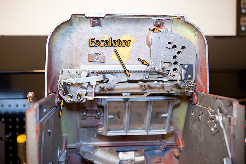
The escalator is essentially the part of the slot machine that accepts coins, makes sure that they are the correct denomination, rejects slugs and determines if the player is using checks. We’ll be disassembling it later, but right now we just want to remove it from the top front casting. It’s held in place by three screws denoted by arrows in the photo above. You might want to save the middle screw for last, just to keep the escalator from swinging out of place while you are removing the screws. Outside of the case, the escalator looks like this:
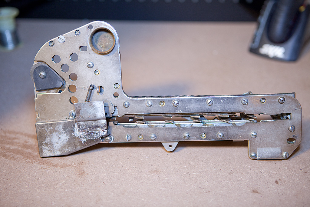
You occasionally see some strange things when looking at escalators. They really aren’t that tough to get working correctly, but some people are lazy. More about that later.
With the escalator removed, we can now get to a couple of pieces of glass on the front casting.
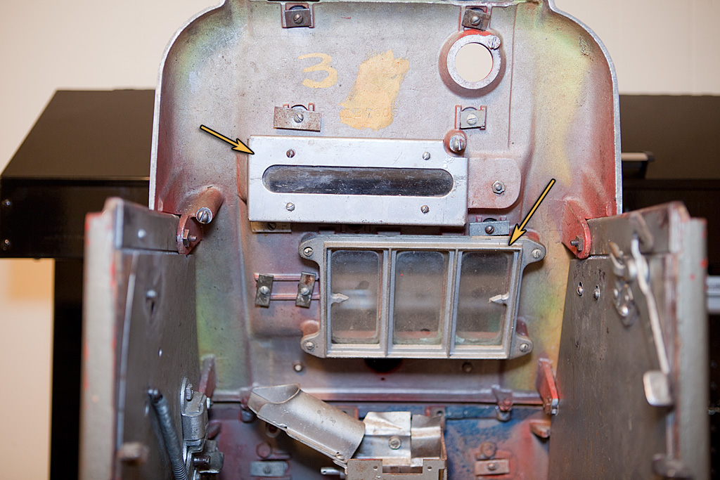
Now, removal of the frames identified above is pretty simple, but you do need to be careful with the glass when you remove the frames or else the glass will fall and break, giving you another item to replace. Often you will need to replace the glass anyway, but there’s no point in being careless. Some people prefer to leave the frames in place, remove the top casting and then deal with the frames with the casting resting flat. Honestly, that’s probably a better approach, but since I removed the frames at this point that’s what I photographed.
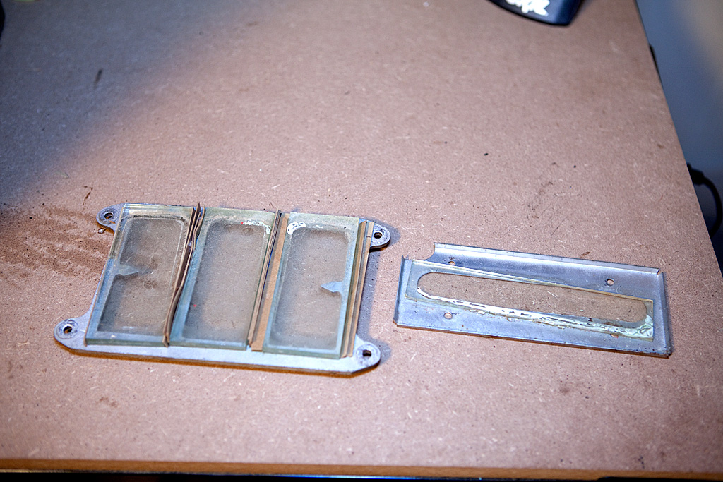
In the photo above you can see that someone has used strips of paper/cardboard as shims to separate the three pieces of glass from the reel windows, and this is pretty typical. Some people tape around the edge of the glass to space it out and keep it from rattling, and generally I think that’s a good idea. We’ll worry about that later, when it comes time to reassemble the case. All of the glass is pretty scratched up, and will probably need to be replaced. There’s nothing magical about the glass, and you can get any glass shop to cut you replacements for a small amount of money. If they don’t have the specific thickness you need, sandwiching a couple of pieces together to get the right thickness is a viable option.
For now, let’s wrap the various pieces of glass in paper or rags to keep it safe and move along to the removal of the top front casting.
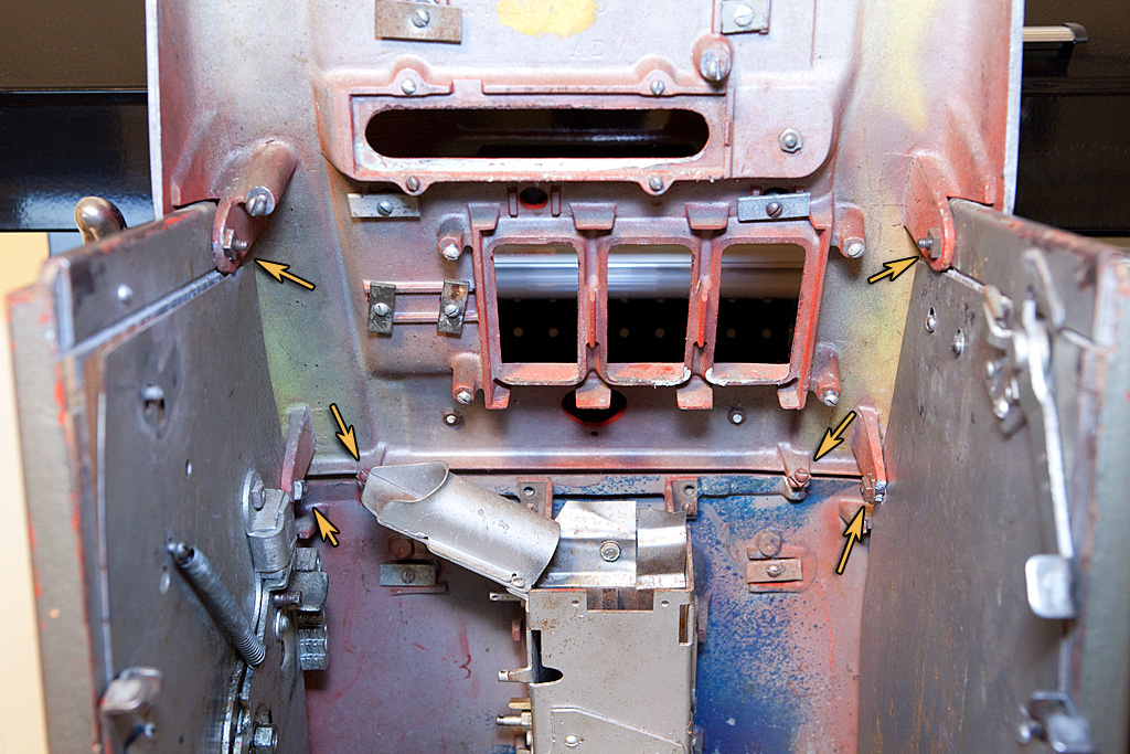
In the photo above you can see that the top front casting is secured in six places. There are two carriage bolts on each side that secure the casting to the sides of the cabinet, plus a pair of screws/nuts that attach it to the bottom front casting. In the photo you can also see that the casting is damaged at the point where lower right carriage bolt is located. This isn’t a huge deal from the perspective of keeping the top front casting on the machine, but it’s definitely not optimal. While not a big enough flaw to justify replacing the casting, it might warrant a repair. As we delve further into the disassembly of the case and cabinet, we’re going to end up with a lot of carriage bolts, so we need to be sure to save them along with the related nuts.
There’s also another situation that I discovered while removing the top front casting, but it will be easier to see a bit further down. For now, let’s take a look at the casting after it’s been removed.

Looking at the arrows above, we can see the damage to the lower right “ear” that is supposed to receive the carriage bolt. We can also see that the two screws intended to secure the top casting to the bottom casting have been bent under rather than going through holes on the bottom casting. These will need to be cut off and replaced… no way around that. In the above photo you can also see the various screws and related hardware that secure the decorative elements found on the front of the machine to the top front casting. There’s really no point in detailing the removal of each of these elements since their removal is really straightforward… just unscrew the screws, remove the elements, and keep the screws/washers with their respective parts.
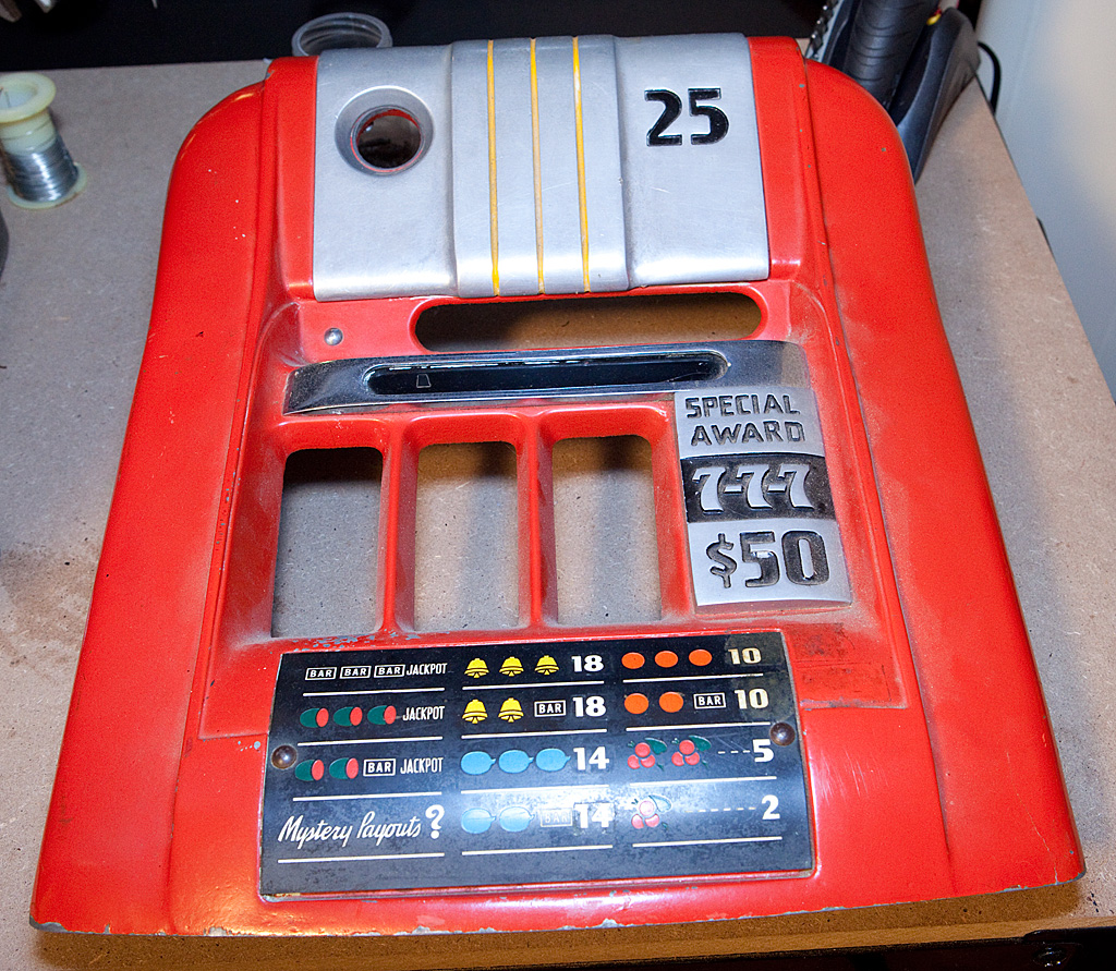
Here’s what the casting looks like from the front:
Now we need to remove the bottom front casting, which should be really simple at this point.
The bottom front casting is secured to the sub-base plate (or should be) by a couple of brackets as indicated by the arrows above. In this case, only one of the brackets is actually in place and secured to the sub-base. Also, if you look at the top of the casting to the right of the jackpot, you can see one of the places that the casting should have been connected to the top front casting by those bent-over screws, but now the story is becoming clear… the “ears” that should have received those screws are broken off. Now, I don’t know for certain, but I’m assuming that someone didn’t know what they were doing, tried to reassemble the case at some point, and just forced the top casting into place which bent the screws and broke off the ears on the bottom front casting.
Stupid, stupid, stupid.
I missed this defect when I was examining the machine before buying it, and it’s exactly the sort of thing I should have been looking for. On the brighter side, however, I was already expecting to replace this casting anyway, just because it doesn’t have the posts necessary to install a gold award dispenser. It’s very likely that the existing casting isn’t original to the machine anyway. I’ll probably have this casting repaired, if possible, for use on another machine at some point in the future.
For now, though, let’s just get the casting free. A long screwdriver can easily access the screws holding the brackets to the front casting, and once they are removed the casting should lift right out.
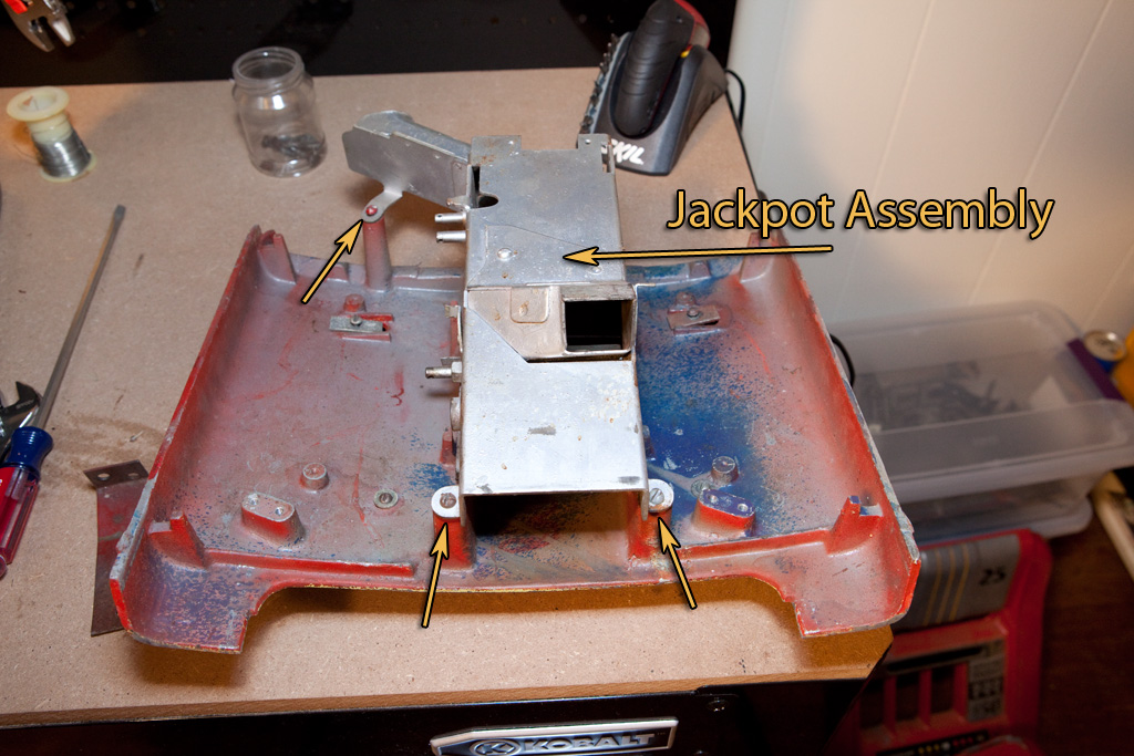
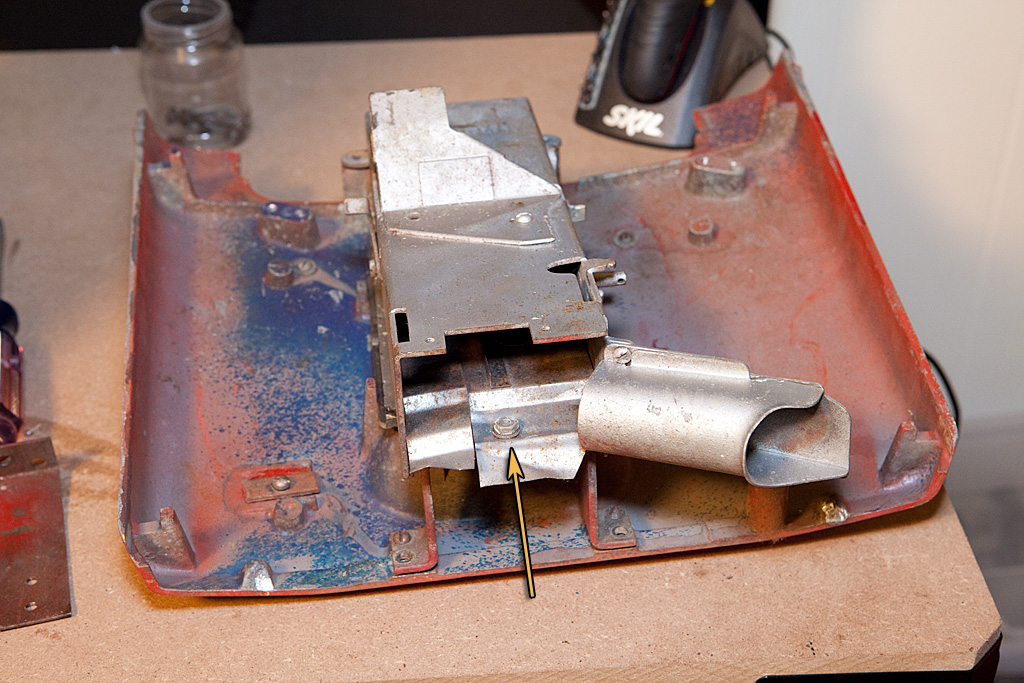
In the photos above, you can see several things. First, the arrows show us the various screws that secure the jackpot assembly to the casting. Removing it will be our next task. Next, we can see the broken ears we’ve been discussing to the right and left of the jackpot assembly in the second photo. There’s no point in crying about that at this point, however, so let’s remove the screws and get the jackpot free of the casting.
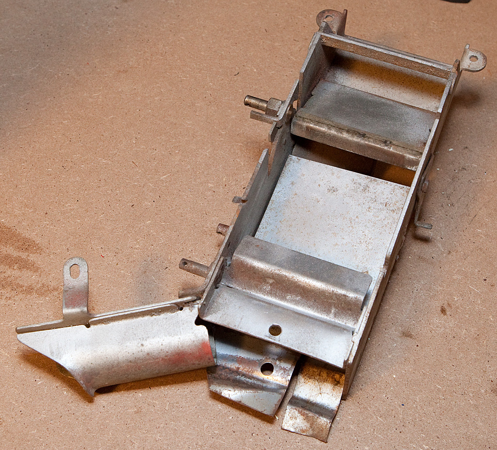
Well, this is technically a jackpot, but it’s missing virtually all of the important parts. This isn’t a surprise… I knew the condition of the jackpot going in. Later on we’ll be looking at the jackpot in more detail.
We left something behind when we removed the jackpot, however, and that’s another piece of glass and some related hardware. With the jackpot assembly gone, the glass and front spacer will lift right off.
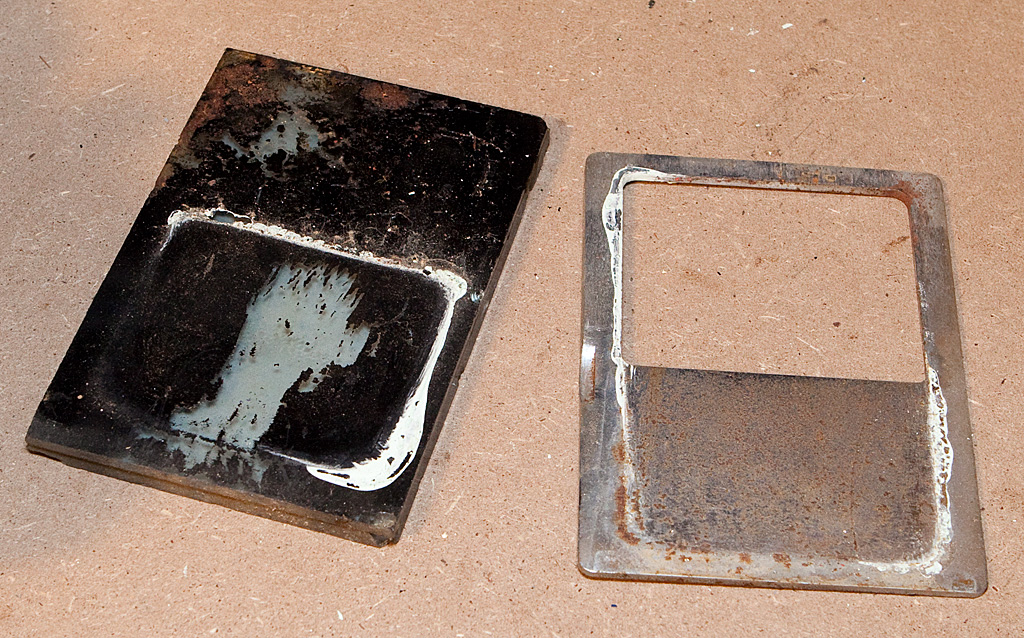
Well, this is just nasty. The glass has been painted black at some point to cover the non-functional jackpot. The front piece is rusted and grimy. It also looks like someone painted at least part of the machine white at some point and didn’t bother to remove the glass or frame before doing so. The glass is a total loss, but we might be able to save the other piece.
As with the top casting, there are a few decorative pieces mounted on the bottom front casting, and these can be removed in the same manner. Just be sure to keep all the screws straight.
Next we’ll start removing the cabinet hardware.